1 clear cmos jumper, 2 internal reserved +5v and +12v connector, Clear cmos jumper – ADLINK MXC-6000 Series User Manual
Page 40: Internal reserved +5v and +12v connector, Table 1-15, Clear cmos jumper settings, Table 1-16, 5v and +12v connector pin functions
28
Introduction
1.7.1
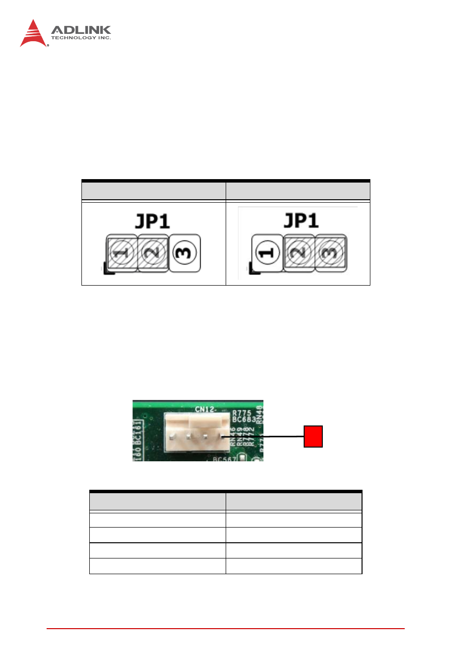
Clear CMOS Jumper
Upon encountering an abnormal condition preventing the
MXC-6000 series from booting, the jumper can clear the BIOS
content stored in CMOS and restore default settings. To clear
CMOS, short pin #2 to pin #3 of JP1 and then return to normal
mode (short pin #1 to pin #2).
Table 1-15: Clear CMOS Jumper Settings
1.7.2
Internal Reserved +5V and +12V Connector
The MXC-6000 series controller provides one power pin header
with +5V and +12V DC power, providing access for PCI and PCI
express card external power supplies..
Table 1-16: +5V and +12V Connector Pin Functions
Normal
Clear
PIN
Signal
1
+5V
2
GND
3
GND
4
+12V
1
See also other documents in the category ADLINK Hardware:
- USB-1901 (84 pages)
- USB-1210 (54 pages)
- USB-2401 (60 pages)
- USB-7230 (50 pages)
- USB-2405 (56 pages)
- DAQe-2010 (92 pages)
- DAQe-2204 (100 pages)
- DAQe-2213 (94 pages)
- DAQe-2501 (74 pages)
- PXI-2010 (84 pages)
- PXI-2020 (60 pages)
- PXI-2501 (62 pages)
- cPCI-9116 (98 pages)
- ACL-8112 Series (93 pages)
- ACL-8112 Series (94 pages)
- ACL-8112 Series (92 pages)
- ACL-8216 (75 pages)
- ACL-8111 (61 pages)
- PCM-9112+ (10 pages)
- PCM-9112+ (94 pages)
- cPCI-6216V (47 pages)
- ACL-6126 (28 pages)
- ACL-6128A (40 pages)
- PCM-6308V+ (52 pages)
- PCM-6308V+ (4 pages)
- PCI-7444 (82 pages)
- PCI-7434 (48 pages)
- PCI-7234 (56 pages)
- PCI-7260 (66 pages)
- PCI-7258 (38 pages)
- PCI-7256 (48 pages)
- PCI-7250 (48 pages)
- LPCI-7250 (48 pages)
- PCI-7396 (65 pages)
- PCI-7296 (59 pages)
- PCI-8554 (67 pages)
- PCIe-7360 (94 pages)
- PCIe-7350 (86 pages)
- PCIe-7300A (114 pages)
- PCIe-7200 (51 pages)
- PCI-7300A (112 pages)
- PCI-7300A (83 pages)
- PCI-7200 (96 pages)
- cPCI-7300 (82 pages)
- cPCI-7300 (83 pages)