Table 1-5, Di channel system interrupt – ADLINK MXC-6000 Series User Manual
Page 30
18
Introduction
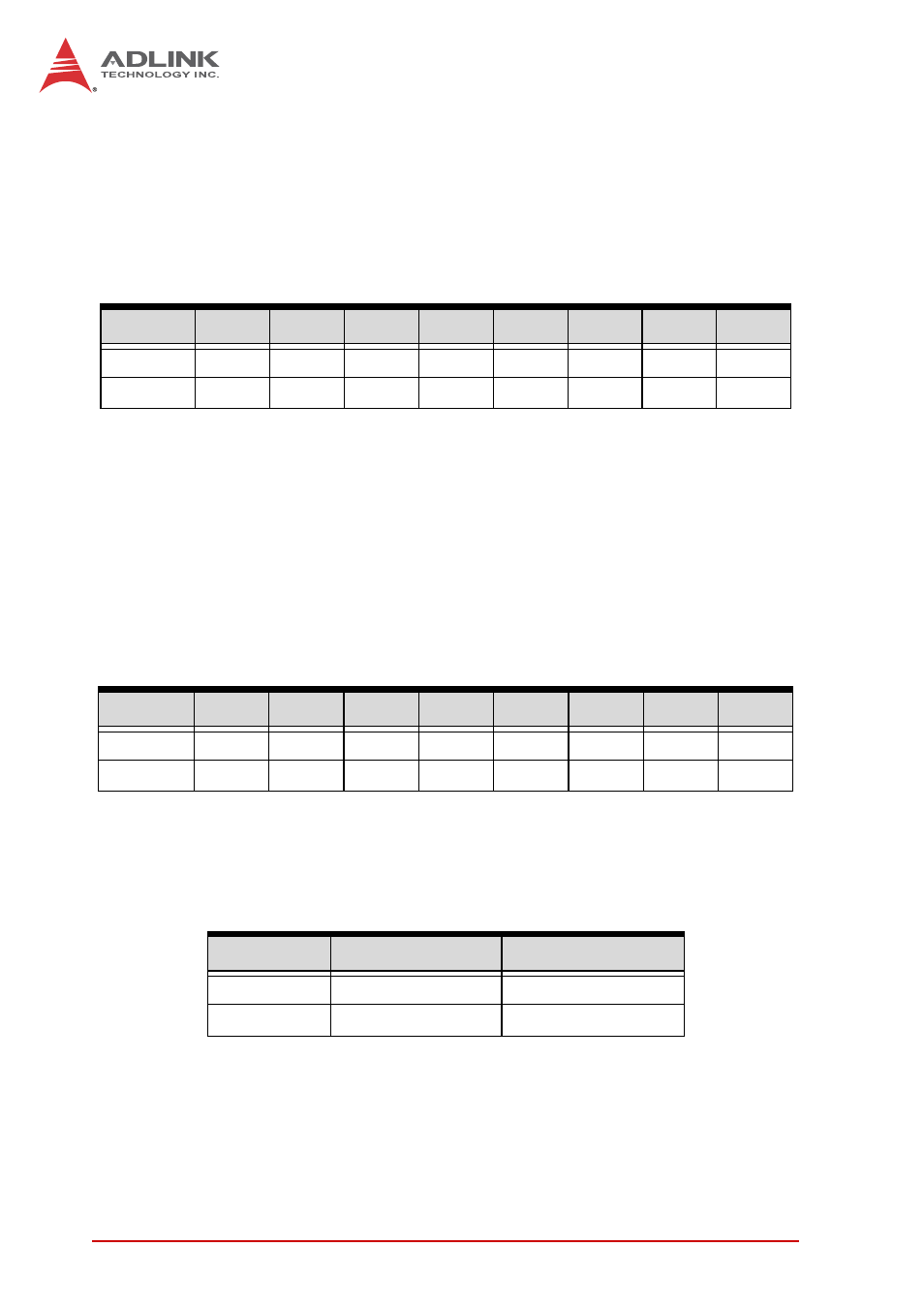
Address: BASE + 0 to BASE + 1
Attribute: read only
Data Format is as follows, wherein IDI_n is Isolated Digital
Input CH n.
Digital Output Register
In the MXC-6000's 16 DO channels, each bit corresponds to a
signal on the digital output channel, based on:
Address: BASE + 0 to BASE + 1
Attribute: write only
Data Format is as follows, wherein IDO_n is Isolated Digital
Output CH n.
System Interrupt for DI Channels 0 and 1
MXC-6000's Digital Input will generate system interrupts when
logic status of DI channels 0 and 1 changes from low to high.
Table 1-5: DI Channel System Interrupt
Sample codes and more interrupt programming information are
available in PCIS-DASK. Please refer to the PCIS-DASK man-
ual.
Bit
7
6
5
4
3
2
1
0
Base + 0
IDI_7
IDI_6
IDI_5
IDI_4
IDI_3
IDI_2
IDI_1
IDI_0
Base + 1 IDI_15 IDI_14 IDI_13 IDI_12 IDI_11 IDI_10 IDI_9
IDI_8
Bit
7
6
5
4
3
2
1
0
Base + 0
IDI_7
IDI_6
IDI_5
IDI_4
IDI_3
IDI_2
IDI_1
IDI_0
Base + 1 IDI_15 IDI_14 IDI_13 IDI_12 IDI_11 IDI_10 IDI_9
IDI_8
DI Channel
Logic Status
System Interrupt
DI 0
From low to high
Generate INT1
DI 1
From low to high
Generate INT2