8 com port connectors, 9 dvi-i connector, Com port connectors – ADLINK MXC-6000 Series User Manual
Page 33: Dvi-i connector, Table 1-8, D-sub 9p signal function of com ports
Introduction
21
MXC-6000
device for operating system files. Installation of a CF card is
described in Section 2.4: Installing CF Cards on page 40.
1.6.8
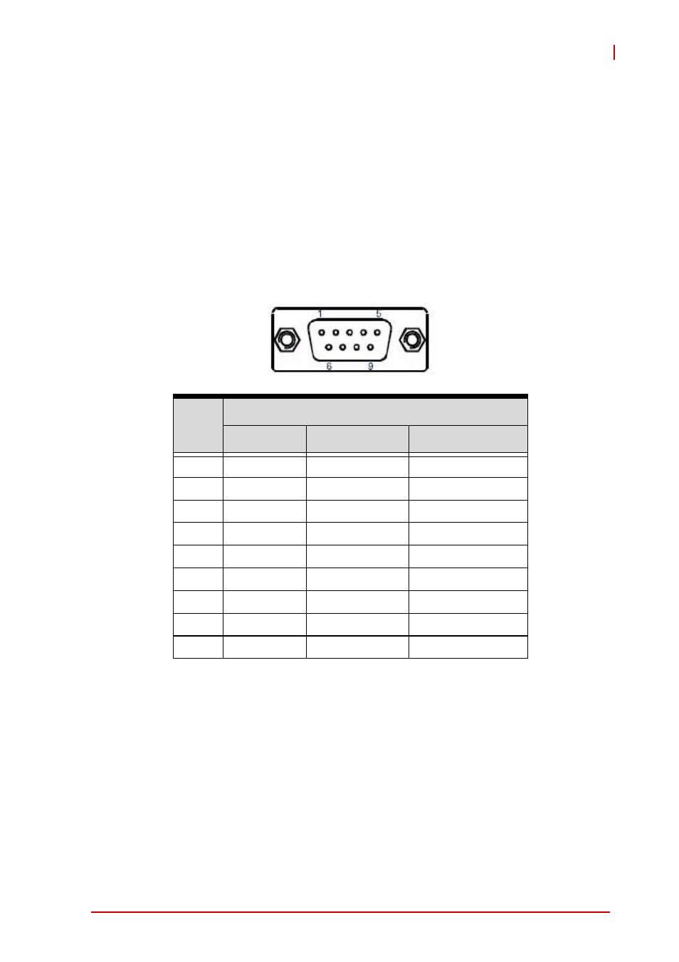
COM Port connectors
The MXC-6000 series controller provides four COM ports through
D-sub 9 pin connectors. The COM1 & COM2 ports support
RS-232/422/485 modes by BIOS setting, while COM3 and COM4
support only RS-232. Please refer to Section B.2.5 on page 61 for
details of BIOS COM port mode settings.
Table 1-8: D-sub 9P signal function of COM ports
1.6.9
DVI-I connector
The MXC-6000 series controller provides one DVI-I connector pro-
viding connection to an external monitor. The DVI-I connector can
be separated into VGA and DVI-D (single link) interfaces using the
included ADLINK Y-cable.
PIN
Signal Name
RS-232
RS-422
RS-485
1
DCD#
TXD422-
485DATA-
2
RXD
TXD422+
485DATA+
3
TXD
RXD422+
N/S
4
DTR#
RXD422-
N/S
5
GND
N/S
N/S
6
DSR#
N/S
N/S
7
RTS#
N/S
N/S
8
CTS#
N/S
N/S
9
RI#
N/S
N/S