1 power button, 2 led indicators, 3 reset button – ADLINK MXC-6000 Series User Manual
Page 22: 6 digital i/o connector, Power button, Led indicators, Reset button, Digital i/o connector, Table 1-1, Front panel i/o connector legend
10
Introduction
Table 1-1: Front Panel I/O Connector Legend
1.5.1
Power Button
The power button is a non-latched push button with a blue LED
indicator. System is turned on when the button is depressed, and
the power LED lights. If the system hangs, depress the button for
5 seconds to turn off the system completely.
1.5.2
LED Indicators
In addition to the LED of the power button, three LEDs on the front
panel indicate the following.
Table 1-2: LED Indicators
1.5.3
Reset Button
The reset button executes a hard reset for the MXC-6000 series
controller.
1.6
Digital I/O Connector
The MXC-6000 controller features an onboard isolated digital I/O
circuit with a 68-pin VHDCI (Very High Density Cable Intercon-
F
Dual Gigabit Ethernet
N
PCI
G
CompactFlash
O
MXC-6101 PCI
MXC-6201 PCI express x4
H
COM port x4
I
DVI-I
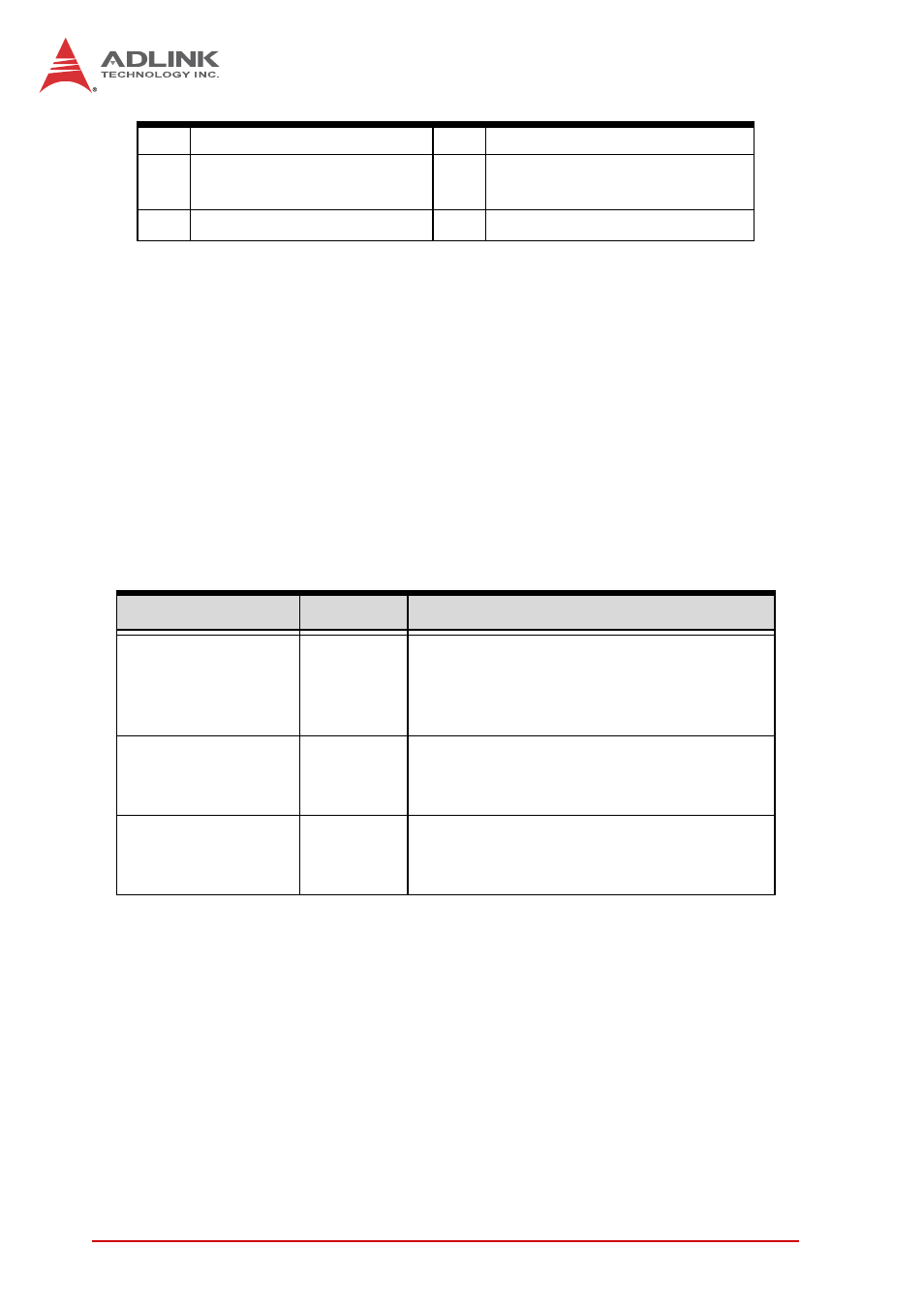
LED indicator
Color
Description
Watchdog (WD)
Yellow
Indicates watchdog timer status. When
watchdog timer starts, the LED flashes.
When the timer is expired, the LED
remains lit..
Hard disk drive
(HD)
Orange
Indicates the HDD operating state.
When the SATA hard drive or CF card is
active, the LED indicator flashes.
CompactFlash
card (CF)
Green
Indicates the operating state of the CF
card on the front panel. The LED
indicator flashes when CF card is active.