2 power distribution, 3 power sequencing, 4 reset – ADLINK aTCA-N700 User Manual
Page 52: Power and reset, 1 power, Consumption budget, Table 10-1 power consumption budget
aTCA-RN710 User's Guide
52
10.2 Power Distribution
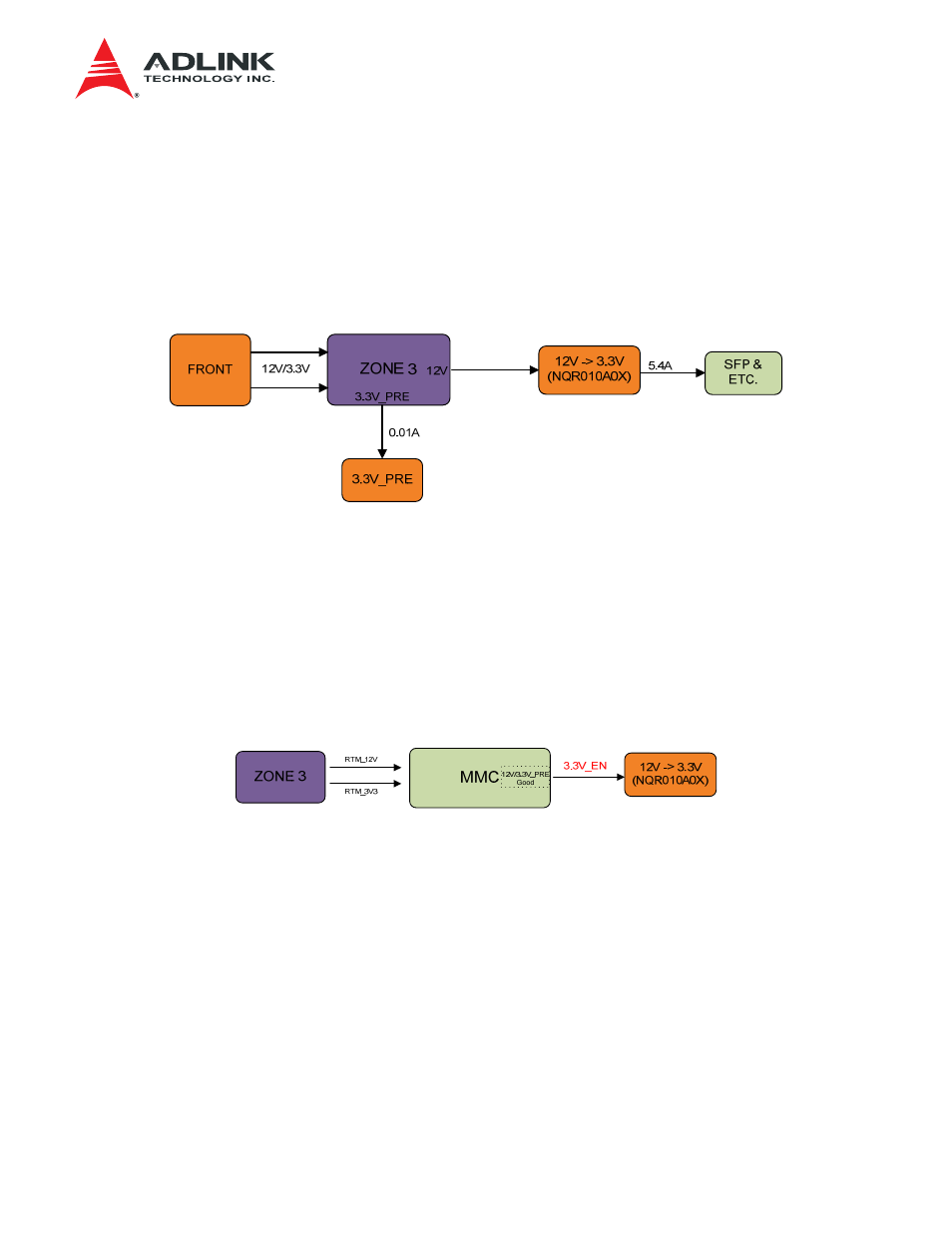
RTM1 receives the powers via a Zone 3 connector from the front blade. 12V and 3.3V_PRE are
available from the Zone connector. The 3.3V_PRE is used for the MMC. The 12V is used as a
source to generated necessary voltages including 3.3V on the board. Shown in Figure 10-1 is the
RTM1 power distribution block diagram.
Figure 10-1 Power Distribution
10.3 Power Sequencing
The power sequencing and monitoring is done by the MMC. The MMC generates 3.3V_EN
enable signal to the DC-DC converter as illustrated in Figure 10-2.
Figure 10-2 Power Sequence
10.4 Reset
Shown in Figure 10-3 is the RTM reset tree. The RTM1 reset commands come from the front
blade, either by an IPMI Reset command or the hardware signals. The hardware signals are
either RTM_ENABLE (Conn P1_H1) or RTM_RESET (Conn P1_H4). The RTM_ENABLE is for
the MMC reset. The RTM_RESET signal is forwarded to the CPLD with passing to the MMC. The
CPLD resets the other devices.