Cpld – ADLINK aTCA-N700 User Manual
Page 46
aTCA-RN710 User's Guide
46
The LED indication is mapped to the LED data values as shown in Table 8-1.
Table 8-1 LED Data and E and L/A LED Indication per Port
LINK-EN
LINK
ACT
Description
E
status
L/A
status
1 1
1
Link-en/Act
ON
BLINK
1 1
0
Link-en/Link
ON
ON
1 0
0
Link-en/No
Link ON
OFF
0
0
0
Link Disable /No Link
OFF
OFF
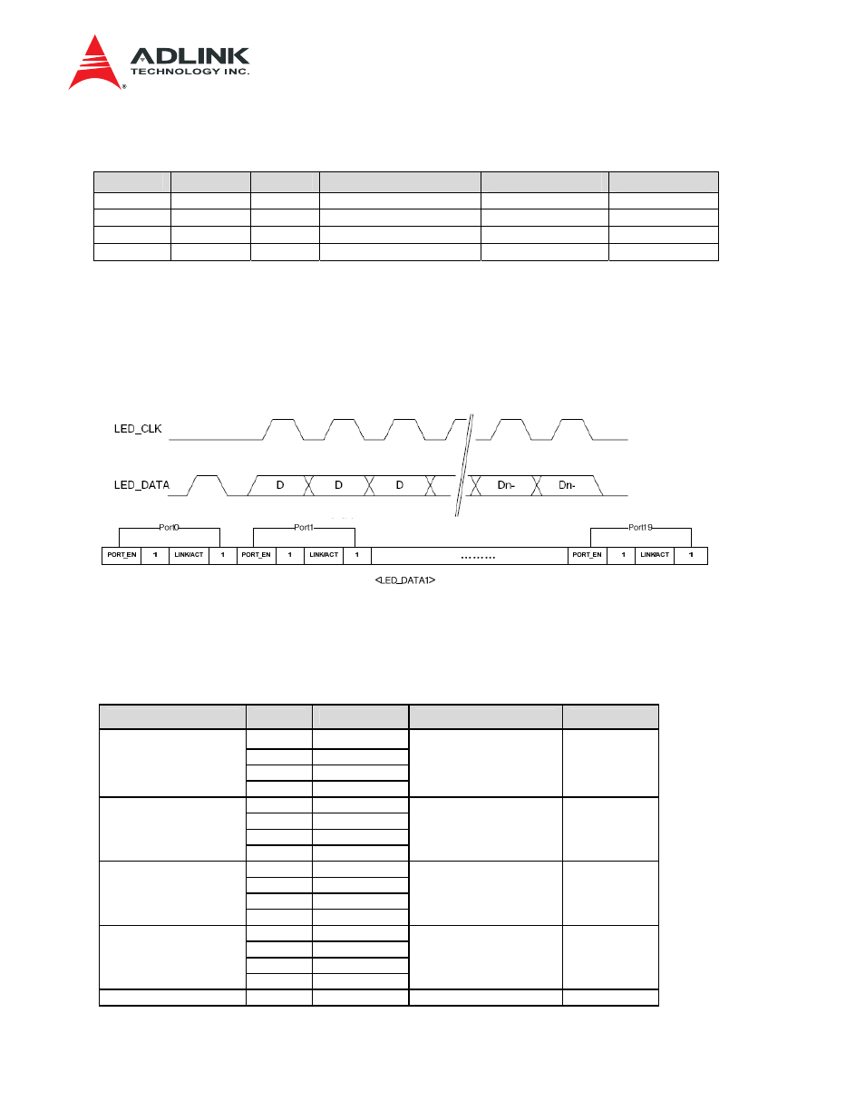
The LED DATA from the Zone 3 connector to the RTM is
RTM_LED_DATA1
,
formatted as in Figure 8-2
where the ports are arranged as in Table 8-2. The preamble is a LED_DATA HIGH pulse without a
clock. The CPLD deserializes the LED data and drives corresponding SFP port LEDs accordingly.
The switch serdes numbers are per aTCA-N700 front blade.
Figure 8-2 Zone 3 RTM_LED_DATA1 format
Table 8-2 LED Data per Port
(F: Front port, R: RTM port, F/R: Shared between Front/RTM)
Data Port No.
DataBit Description
Switch Serdes No.
Port Name.
0 PORT_EN
1 1
2 LINK/ACT
Port 0
3 1
57 R-P01
4 PORT_EN
5 1
6 LINK/ACT
Port 1
7 1
58 R-P02
8 PORT_EN
9 1
10 LINK/ACT
Port 2
11 1
59 R-P03
12 PORT_EN
13 1
14 LINK/ACT
Port 3
15 1
60 R-P04
Port 4
16
PORT_EN
53
R-P05