7 module management controller, 1 overview, 2 features and functions – ADLINK aTCA-N700 User Manual
Page 35: 4 port, Mapping, Table 6-1 service port mapping
aTCA-RN710 User's Guide
35
7 Module Management Controller
7.1 Overview
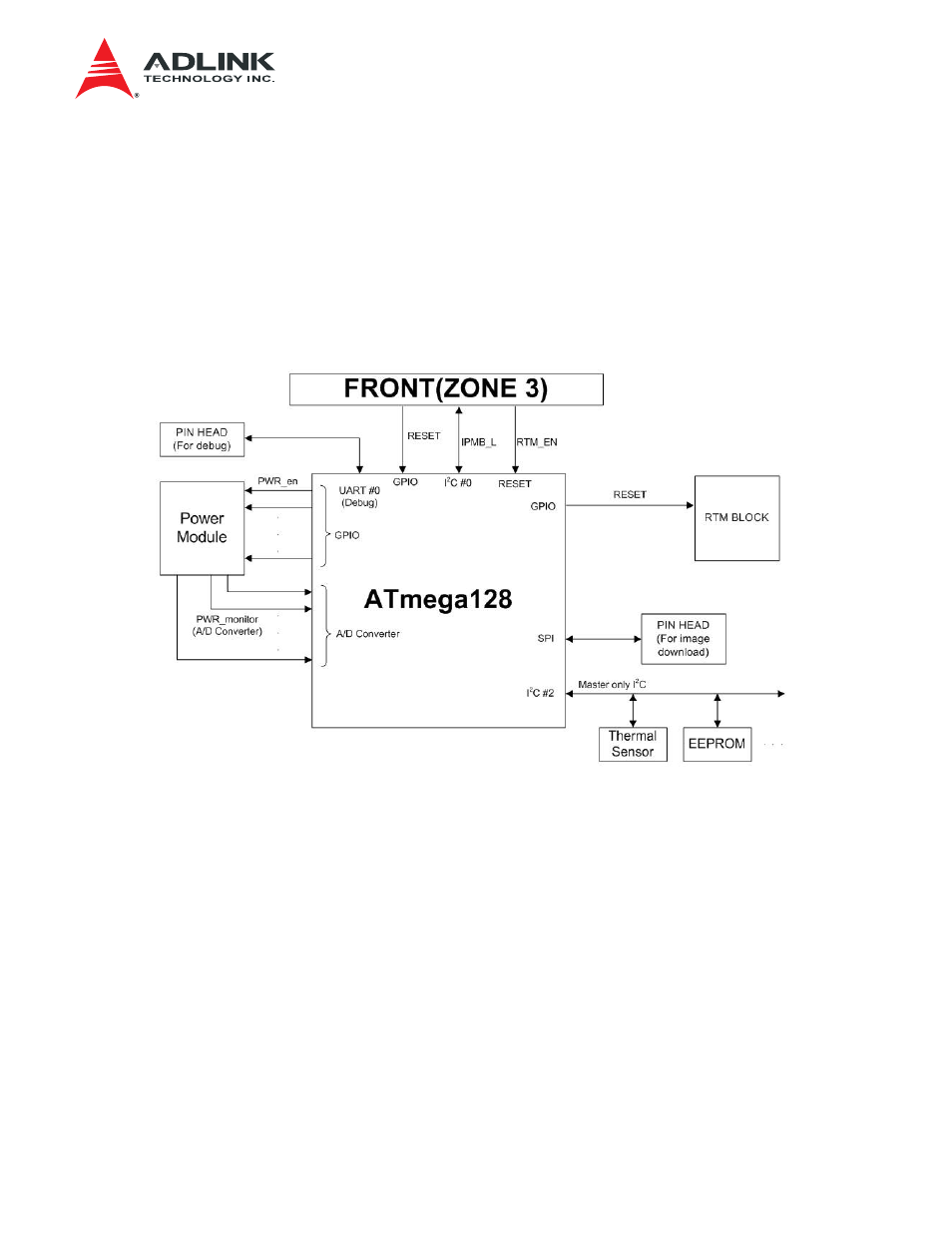
Figure 7-1 shows the Module Management Controller (MMC) and its associated components. The
MMC is responsible for the RTM chassis management functions compliant to IPMI v2.0 specifications.
The MMC interfaces with the IPMC on the front blade through the IPMB-L on the Zone 3 connector to
exchange IPMI commands. The Interface with the CPLD is via the GPIO pins. The power distribution
and monitoring of the voltage rails are the critical functions of the MMC.
Figure 7-1 MMC Block Diagram
7.2 Features and Functions
Itemized below are the features and the functions of the MMC.
• RTM
Management
9
Intelligent RTM depends on the MMC.
9
MMC communicates with the front blade IPMC via IPMB-L through a Hot-swap buffer: FR
U information and Commands are exchanged.
• Programmable device (CPLD) Download Interface
9
The CPLD programming interface is connected to the MMC GPIO. Upon request from the
IPMC, the MMC initiates the programming of the CPLD image downloaded to the RTM
via IPMB-L interface.