Table 7-6 signals: rtm activate procedure, Ipmc lmp, Atca-rn710 user's guide – ADLINK aTCA-N700 User Manual
Page 41: Shutdown triggered by lmp, Figure 7-7 shutdown procedure, Table 7-7 signals: shutdown procedure, Rtm shutdown triggered by lmp, Figure 7-8 rtm shutdown procedure
aTCA-RN710 User's Guide
41
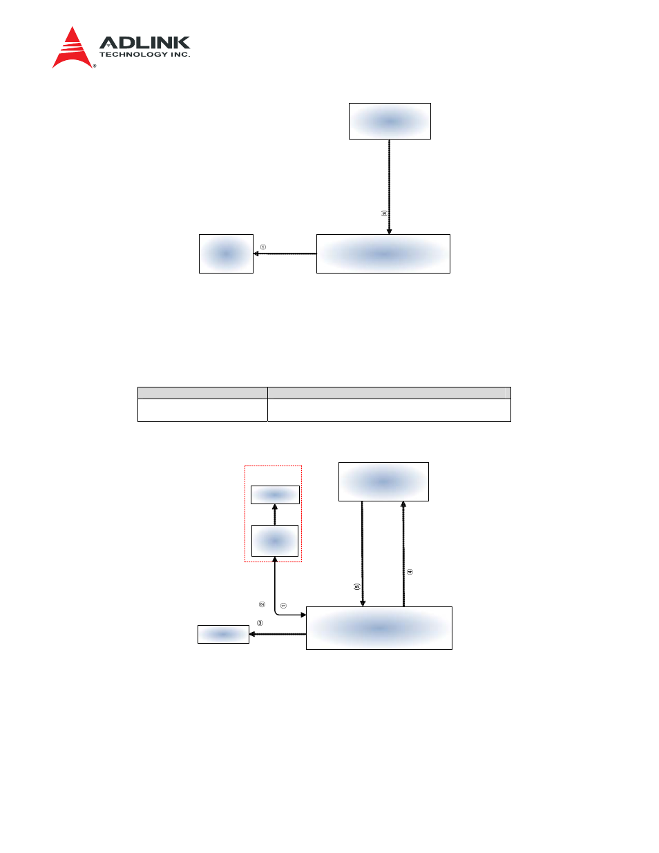
Shutdown triggered by LMP
Power OFF
Sh
utd
o
wn
C
M
D
IPMC
LMP
UART#1
Power
Sequence
P5(5)
PAYLOD In
ter
fa
c
e
Figure 7-7 Shutdown Procedure
⒮
LMP sends Shutdown Command to IPMC via PAYLOAD Interface (UART).
①
IPMC initiates Power Down sequence to turn off Blade and RTM power.
Table 7-7 Signals: Shutdown Procedure
Signal Name
Status
PAYLOAD Interface
P5(4),P5(5)
Shutdown Command
- IPMI Message
RTM Shutdown triggered by LMP
RT
M
P
o
we
r
OFF
RTM Power
OFF
RTM
Disable
RTM
_
Shutd
o
w
n
C
M
D
IPMC
LMP
MMC
P5(4)
P5(5)
P8(0,1)
RTM DC/DC
PC(0)
RTM
Pow
e
r
OFF Done
PAYLO
A
D
Interface
IPMB-L
PD(0,1)
RTM POWER
RTM SIDE
P1(4)
Figure 7-8 RTM Shutdown Procedure
⒮
LMP sends RTM Shutdown to IPMC via PAYLOAD Interface (UART).
①
IPMC sends RTM Power OFF to MMC via IPMB-L.
②
MMC completes RTM Power OFF operation and sends the completion message to IPMC.
③
IPMC turns off RTM Power 12V.
④
IPMC sends RTM Disable information to LMP via PAYLOAD Interface (UART).