5 architecture overview, 8 hpm, Upgrade – ADLINK aTCA-N700 User Manual
Page 30: Zone 3, Atca-rn710 user's guide, Figure 5-1 rtm1 architecture
aTCA-RN710 User's Guide
30
5 Architecture Overview
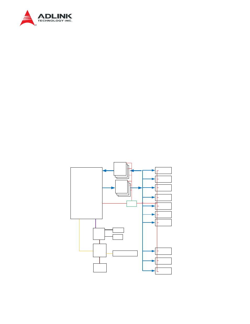
The aTCA-RN710 is composed of several major components as illustrated in Figure 5-1: the MMC,
the CPLD, the Retimers, the I2C Block and the SFP+s. The SFP+ optic ports and the Retimers
GN2405A from Gennum play a major role in the data plane. The data plane components are
connected via the SFI interface, where 10Gbps data rate is supported by a pair of Serdes lanes per
port. Since the SFI signals according to SFF8431 specification are not intended to travel over a
backplane, the use of a retimer with equalizer function is essential to compensate the signals. The
equalizer function of the Retimer compensates any frequency dependent loss on the path to extend
the reachability of sensitive SFI signals on the board. The retimer function recovers clean edges of
the signal distorted due to unwanted reflections on the impedance mismatch points such as the vias
and the connectors along the traces on the board. The GN2405A on the board has both functions.
The GN2405A supports two ports, thereby the board needs six devices to support 12 SFP+ ports,
which result in 12 SFI TX links from the front blade to the RTM and another 12 SFI RX links from the
RTM to the front blade. At the center of the control functions, there exists the Module Management
Controller or the MMC. The MMC is responsible for the RTM management and interfaces with the
front blade IPMC via IPMB-L to exchange management commands, and the FRU information’s and
the status. The CPLD sits in between the MMC and the devices to distribute the control signals such
as Enable/Disable and Resets and collect various signals for the MMC. The I2C HUBs inside the I2C
Block are used to extend a limited I2C bus from the Zone 3 connector to control many devices by
duplicating its primary I2C Bus into secondary I2Cs.
SFI (Rx)
Port1
Port2
Port3
Port10
Port11
Port12
IPMB_L
LMP I2C
MMC
CPLD
Service Port
LED
RST
RST
LOGIC
Zone 3
MUX
SFI (Tx)
Port4
Port5
Port6
Port7
.
.
.
.
SFI
SFI
SFI
LED Control
PWR
Mgmt.
GN2405
A
GN2405
A
SFI (Tx)
SFI (Rx)
Figure 5-1 RTM1 Architecture