2 dip switches, 2 hardware installation, 1 front blade – ADLINK aTCA-N700 User Manual
Page 14: 2 rtm, Installation and operation, 1 hardware, Configuration setting, 1 headers/jumpers, Hardware installation
aTCA-RN710 User's Guide
14
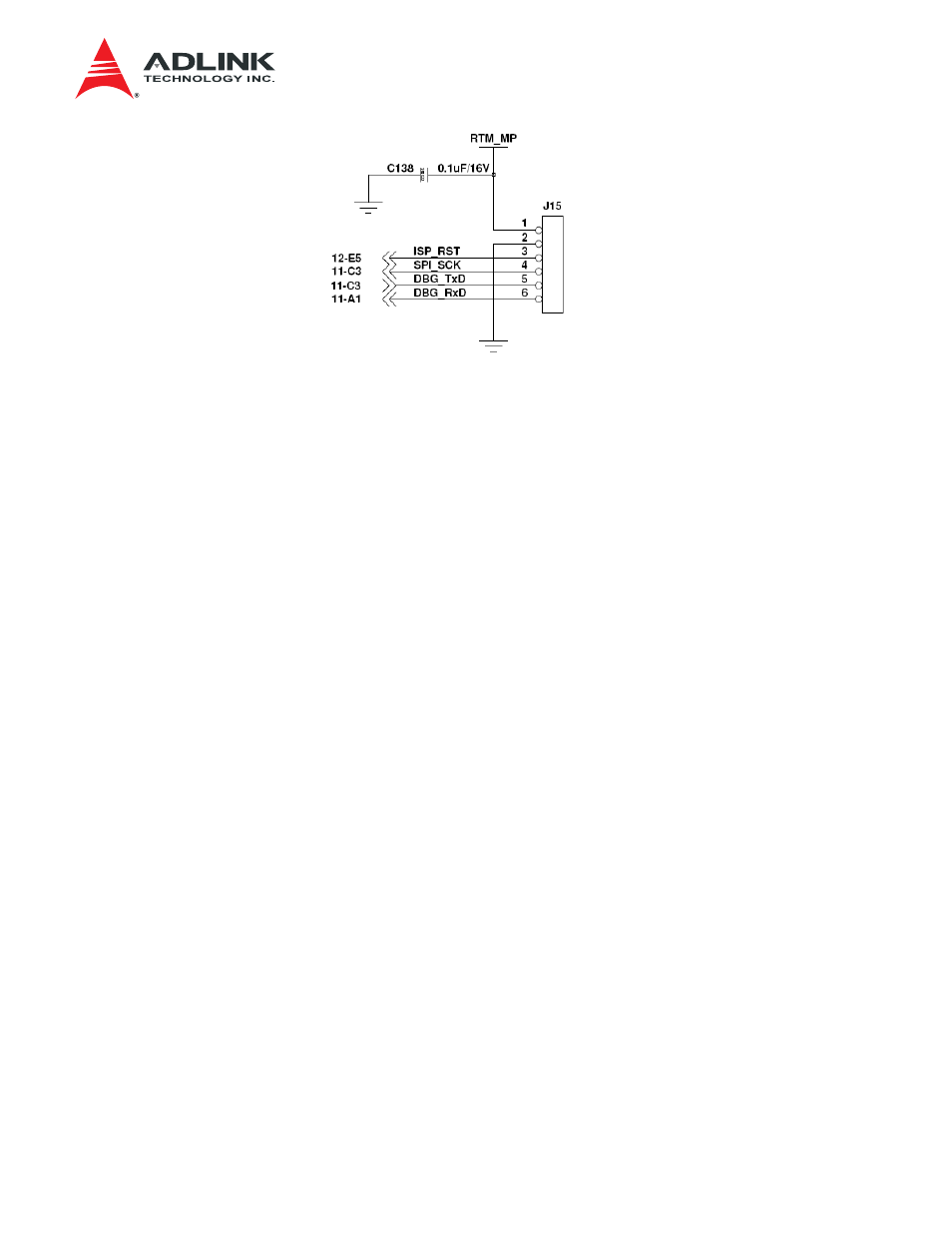
Figure 4-2 Header J15
4.1.2 DIP
Switches
SW1 is provided for the MMC to select different I/O connection between the ISP interface and the
UART interface during the debugging phase.
• MMC to UART: Close pin 1 and pin2.
• MMC to ISP interface: Open pin 1 and pin2
4.2
Hardware Installation
The steps required to install the aTCA-RN710 are the following: Front Blade installation, RTM
plugging-in, Monitoring Station Connection, and Traffic Port connection.
4.2.1 Front
Blade
For front blade installation, refer to the front blade user's manual.
4.2.2 RTM
The board should be plugged in using the following procedures:
Step 1: The injector handles (top and bottom) shown in Figure 4-3
should be opened to plug the
board into a chassis slot.
Step 2: The board should be aligned on to the rail, marked as (A), in the slot reserved for the board.
Step 3: Slide the board into the chassis until the guide of the faceplate and the hole of the chassis
meet as in (B)
Step 4: Once the guide of the faceplate slides into the hole, close the upper injector handle so that
the handle wedge goes into the handle hole and makes a click sound.