2 vga interface, 3 ethernet connection, Vga interface – ADLINK aTCA-9700 User Manual
Page 22: Ethernet connection
22
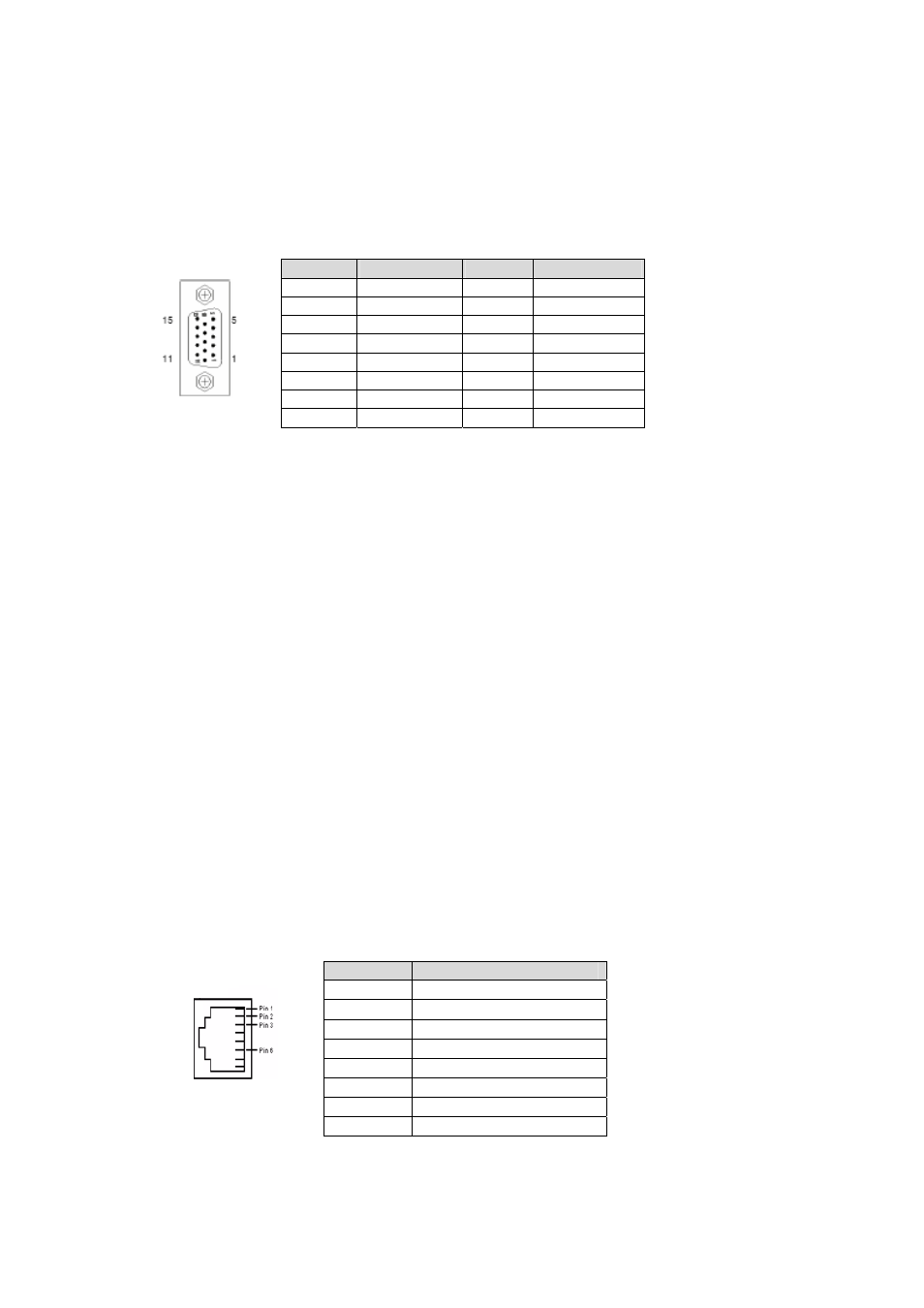
3.3.2 VGA
Interface
A DB-15 female connector on the front panel provides analog display output.
Front Panel VGA Pin Definition (DB-15)
3.3.3 Ethernet
Connection
The aTCA-9700 is equipped with one dual-port Intel® I350 AM2 Gigabit Ethernet Controller
and one dual-port Intel® 82576EB Gigabit Ethernet Controller which provide four GbE ports
in total. In default configuration, two ports from the Intel® I350 AM2 Gigabit Ethernet
Controller are connected to the front panel RJ-45 ports. Two GbE ports from the Intel®
82576EB Gigabit Ethernet Controller are connected to Zone 2 Base Channels 1 and 2
(BCH1/BCH2).
Two Mellanox ConnectX-3 40G network controllers are installed on the aTCA-9700
providing four 40GBASE KR4 links to Fabric Channels 1,2,3 and 4. The four 40GBASE-
KR4 links are divided into two groups. FCH1/3 are connected to one of the ConnectX-3
40G network controllers while FCH2/4 are connected to the other.
Note: The bandwidth of each ConnectX-3 40G network controller is limited by the PCIe x8
Gen3 link to the CPU. The total bandwidth of each ConnectX-3 40G network controller is
approximately 50Gb/s.
With the aTCA-R9700 RTM installed, the aTCA-9700 supports six 10GbE SFP+ ports from
the Intel 82599ES Network Interface Controllers.
Front Panel GbE Pin Definition (RJ-45)
Pin
GbE Signal Names
1
Transmit Data1 +
2
Transmit Data1 -
3
Receive Data2 +
4
Receive Data3 +
5
Receive Data3 -
6
Receive Data2 +
7
Transmit Data4 +
8
Transmit Data4 -
Pin
Name
Pin
Name
1 RED 9 +5v
2 GREEN 10 GND
3 BLUE 11 NC
4 NC 12
DDC_DATA
5 GND 13
HSYNC
6 GND 14
VSYNC
7 GND 15
DDC_CLK
8 GND