Figure 3-6, Post-trigger acquisition, Figure 3-7 – ADLINK PXIe-9529 User Manual
Page 32: Delay trigger mode acquisition
22
Operations
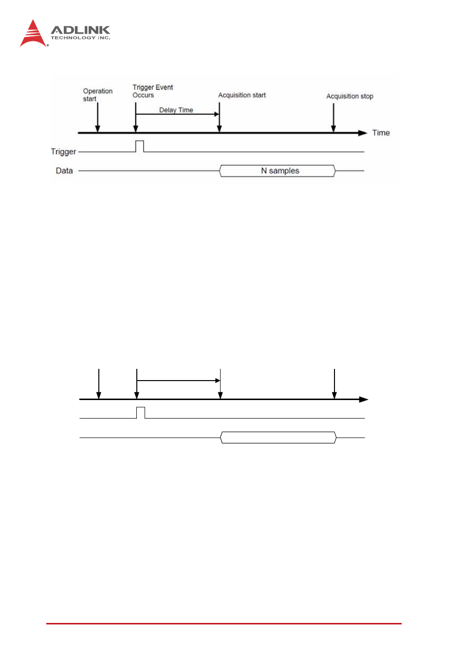
Figure 3-6: Post-Trigger Acquisition
Delay Trigger Mode
If delay trigger mode is configured, delay time from when the
trigger event asserts to the beginning of the acquisition and
waveform generation can be specified, as shown. Delay time is
specified by a 32-bit counter value with the counter clocking
based on the PCIe clock. Accordingly, maximum delay time is
the period of PCIe_CLK X (2^32 - 1) and minimum is the period
of PCIe_CLK (8 ns).
Figure 3-7: Delay Trigger Mode Acquisition
Post-Trigger or Delay-Trigger Acquisition with Re-Trigger
Post-trigger or delay trigger acquisition with re-trigger function
enables collection of data after several trigger events, as
shown. When the number of triggers is defined, the PXIe-9529
acquires specific sample data each time a trigger is accepted.
All sampled data is stored in onboard memory first, until all trig-
ger events have occurred, such that time between the previous
sampled data and the subsequent trigger event can be only
Time
Operation
start
Trigger
Data
Trigger Event
Occurs
Acquisition stop
Begin to transfer data to
system
N samples
Acquisition start
Delay Time