3 trigger source and trigger modes, Trigger source and trigger modes, Figure 3-3 – ADLINK PXIe-9529 User Manual
Page 28: Trigger architecture, 18 operations, Figure 3-3: trigger architecture
18
Operations
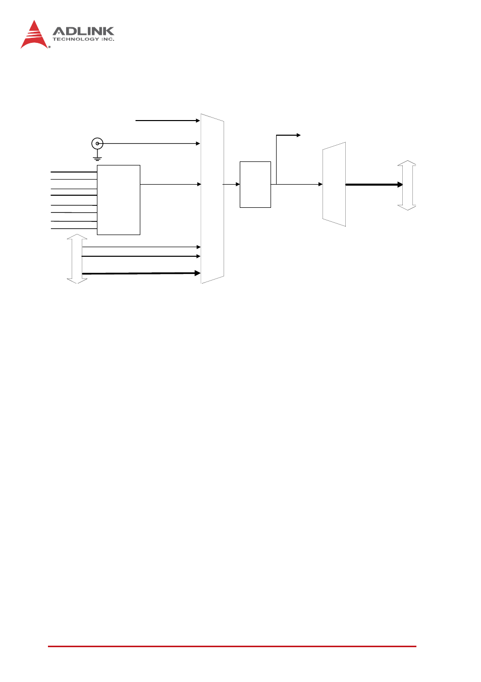
3.3 Trigger Source and Trigger Modes
Figure 3-3: Trigger Architecture
The PXIe-9529 requires a trigger to implement acquisition of data.
Configuration of triggers requires identification of trigger
source. The PXIe-9529 supports internal software trigger, external
digital trigger, PXI_STAR trigger, PXIe_DSTARB, PXI Trigger Bus
[0.7], and SSI bus as well as analog trigger.
Software Trigger
The software trigger, generated by software command, is
asserted immediately following execution of specified function
calls to begin the operation.
External Digital Trigger
An external digital trigger is generated when a TTL rising edge
or a falling edge is detected at the SMB connector on the front
panel. As shown, trigger polarity can be selected by software.
Note that the signal level of the external digital trigger signal
should be TTL compatible, with minimum pulse width 10ns.
Trigger Source Mux
Analog
Trigger
PXI In
te
rfa
ce
PXI_STAR
PXI Trigger Bus[0:7]
Software Trigger
Analog CH0
Analog CH1
TRG IN
SMB Connector
Digital Trigger Input
Trigger
Decision
Tri
gger Output Mux
PXI Trigger
Bus[0:7]
PXI Interface
SSI_TRIG1
SSI_TRIG2
SSI_START_OP
To Internal FPGA
Circuit
Analog CH2
Analog CH3
Analog CH4
Analog CH5
Analog CH6
Analog CH7
Analog
Trigger
Selection
PXIe_DSTARB