Analog trigger, Figure 3-6, Analog trigger conditions – ADLINK PXIe-9848 User Manual
Page 31
Operations
21
PXIe-9848
serves as a master module and can output trigger signals to the
PXI Trigger Bus Numbers 0 through 7.
Analog Trigger
PXIe-9848 analog trigger circuitry can be configured to monitor
one analog input channel from which data is acquired. Selection of
an analog input channel as the analog trigger channel does not
influence input channel acquisition. The analog trigger circuit gen-
erates an internal digital trigger signal based on the condition
between the analog signal and the defined trigger level.
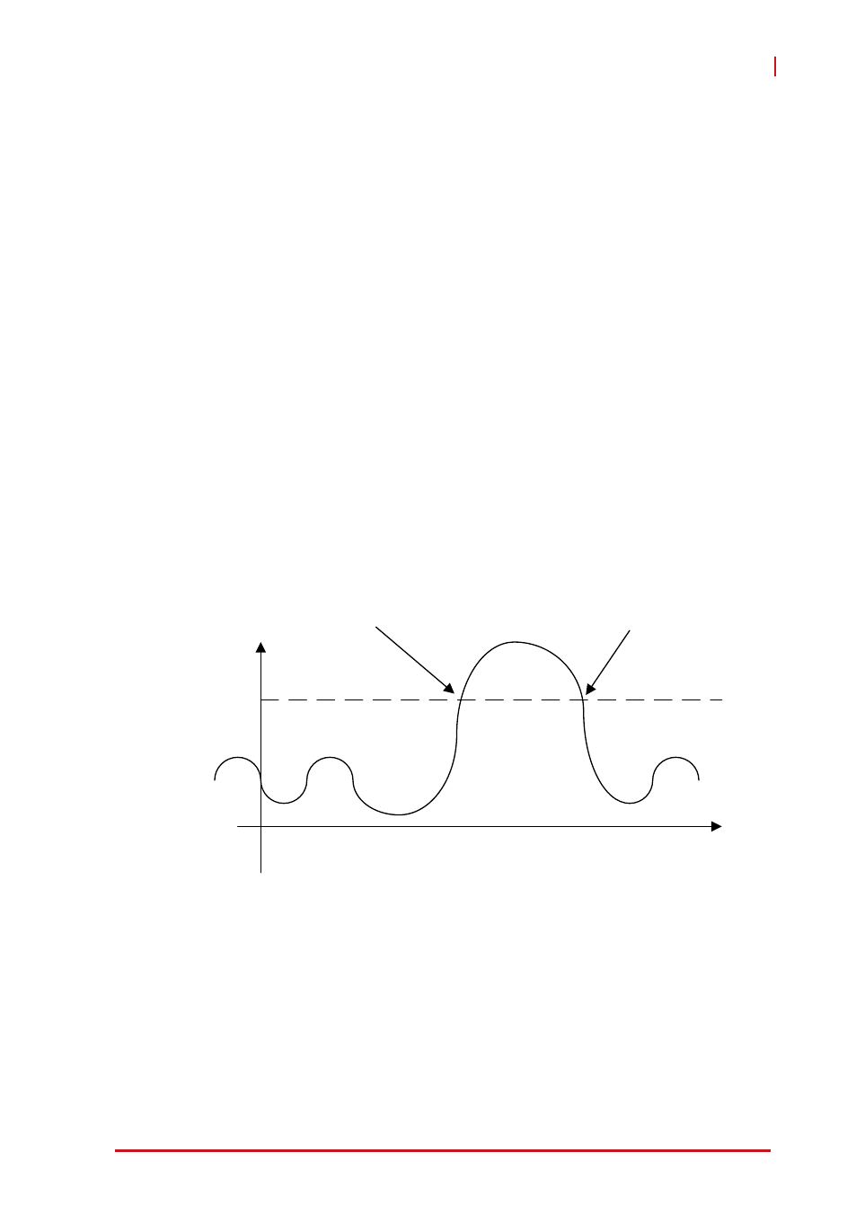
Analog trigger conditions are either positive-slope trigger, in which
the trigger event occurs when the analog input signal changes
from a voltage lower than the specified trigger level to a voltage
exceeding the specified trigger level, or negative-slope trigger, in
which the trigger event occurs when the analog input signal
changes from a voltage exceeding the specified trigger level to a
voltage lower than the specified trigger level.
Figure 3-6: Analog Trigger Conditions
The trigger signal can be chosen from among CH0, CH1, CH2,
CH3, CH4, CH5, CH6 and CH7 while using an external analog
Trigger Level
Positive-Slope Trigger Event
Occurs
Negative-Slope Trigger
Event Occurs
Analog
Signal