Pxi star trigger, Pxie_dstarb trigger, Pxi trigger bus – ADLINK PXIe-9848 User Manual
Page 30: Figure 3-5, External digital trigger configuration
20
Operations
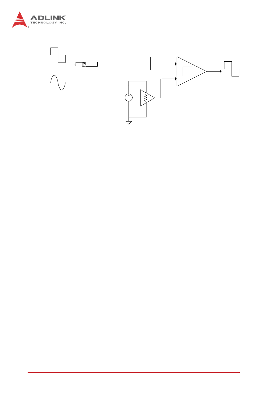
Figure 3-5: External Digital Trigger Configuration
PXI STAR Trigger
When PXI STAR is selected as the trigger source, the
PXIe-9848 accepts a TTL-compatible digital signal as a trigger sig-
nal. Triggering occurs when a rising edge or falling edge is
detected at PXI STAR, with trigger polarity configurable by soft-
ware. The minimum pulse width requirement of this digital trigger
signal is 20 ns.
PXIe_DSTARB Trigger
The PXIe_DSTARB signal, a differential signal transmitted via the
PXI Express Chassis backplane, distributes high-speed,
high-quality trigger signals. When PXIe_DSTARB is selected as
the trigger source, the PXIe-9848 accepts a fast-switching LVDS
digital signal as a trigger signal. Triggering occurs when a rising
edge or falling edge is detected at PXIe_DSTARB, with trigger
polarity configurable by software, with minimum pulse width
requirement of 20 ns.
PXI Trigger Bus
The PXIe-9848 utilizes PXI Trigger Bus Numbers 0 through 7 to
act as a System Synchronization Interface (SSI). With the inter-
connected bus provided by PXI Trigger Bus, multiple modules are
easily synched. When configured as input, the PXIe-9848
serves as a slave module and can accept trigger signals from one
of buses 0 through 7. When configured as output, the PXIe-9848
Trigger IN
High Speed
Comparator
3.3VDC
Protection Circuit
Trigger Threshold
Adjustment
OR