Pwr2, Ar-v5430fl installation guide, Reserve – Acrosser AR-V5430FLAT User Manual
Page 24
AR-V5430FL Installation Guide
JP2
Define KEY_SW, ENG_STS input type
STATUS
SETTING
Open
High_active
Short
Low_active
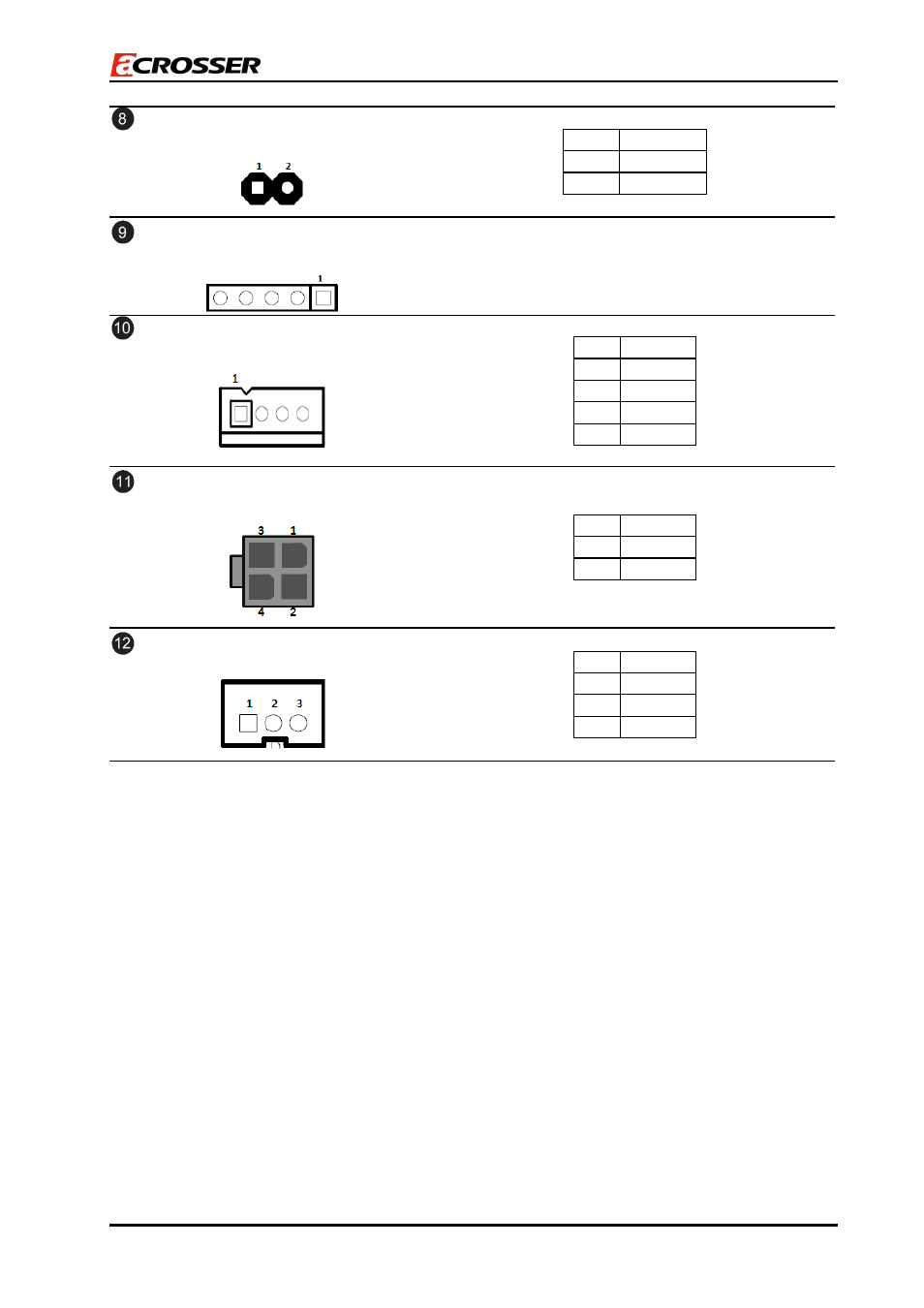
J5
Microchip programming connector
Reserve
PWR4
12V(Max 2A), 5V(Max 2A) output
PIN
SIGNAL
1
+12V
2
GND
3
GND
4
+5V
PWR2
Main +12V(Max 8A) output
PIN
SIGNAL
1,2
GND
3,4
+12V
COM1
Simple UART connector
PIN
SIGNAL
1
RX
2
Tx
3
GND
NOTE1: (For detailed functions, please refer to the User Manual.)
PWRBTN_IN: Trigger
power-up
at Mode0, Mode5, Mode6, Mode7
LOC_SW:
Main system on/off switch
1. Short: System off
2. Open: System on (default)
KEY_SW:
Trigger power-up at Mode2, Mode3, Mode4
ENG_STS:
Detect the status of the main system.
STS_LED:
Indicate power status.
Note2: (For detailed functions, please refer to the User Manual.)
Mode0: ATX function
Mode1: AT function
Mode2, Mode3, Mode4: Smart ATX (power-on by trigger KEY_SW)
Mode5, Mode6, Mode7: Smart ATX (power-on by trigger PWRBTN_IN)
24/39