Acrosser AR-B1894 User Manual
Page 15
2.3 Jumpers/Connectors
Setting
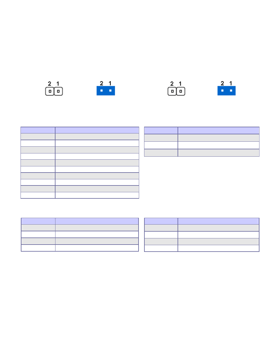
2.3.1 RTC CMOS Clear Select (JP1)
2.3.2 CPU Frequency Select (JP4)
OPEN
Normal Operation
SHORT
Clear CMOS
contents
OPEN
400 MHz
SHORT
533 MHz
2.3.3 Internal Audio for Chassis (AUDIO1)
2.3.4 Audio Connector (AUDIO2)
PIN No.
Description
1
F_MIC1
2 Ground
3
F_MIC2
4 +5V
5
LOUTR
6 F_R
7
NC
8 NC
9
LOUTL
10 F_L
PIN No.
Description
1 (Blue)
Line-in
2 (Green)
Speaker out
3 (Red)
MIC-in
2.3.5 CD-In from CD-ROM (CD1)
2.3.6 Chassis/CPU/System Connectors
(CHS_FAN1, CPU_FAN1, SYS_FAN1)
PIN No.
Description
1
CD-L
2 CD-Ground
3
CD-Ground
4 CD-R
PIN No.
Description
1
GND
2 +12V
3
SENSE
4
Control (CPU_FAN1 only)
See also other documents in the category Acrosser Computer Accessories:
- AR-N6000 (28 pages)
- AND-D525N2 (38 pages)
- AND-D525N2 (30 pages)
- ANR-IB75N1/A/B (76 pages)
- ANR-IB75N1/A/B (60 pages)
- ANR-IH61N1/A/B (57 pages)
- ANR-IH61N1/A/B (73 pages)
- AR-R6000 (32 pages)
- AR-R6000 (22 pages)
- AR-ES0631ET (11 pages)
- AR-ES0631ET (15 pages)
- AR-R5800 (58 pages)
- AR-R5800A (40 pages)
- AR-R5800 (40 pages)
- AR-R5800 (40 pages)
- AR-R5800 (58 pages)
- AR-R5800 (58 pages)
- AR-N8601 (31 pages)
- AR-N8601 (10 pages)
- AR-R5700 (13 pages)
- AR-R6006 (35 pages)
- AR-R6006 (24 pages)
- AR-R6006 (35 pages)
- AR-R6006 (24 pages)
- AR-R8601E16 (8 pages)
- AR-N8601FL (37 pages)
- AR-N5205A (13 pages)
- AR-R5205FL (12 pages)
- AR-R5500 (10 pages)
- AR-B1551 (34 pages)
- AR-B1550 (32 pages)
- AR-B1550 (32 pages)
- AR-B1550 (32 pages)
- AR-B1550 (37 pages)
- AR-B1551 (37 pages)
- AR-B1551 (37 pages)
- AR-B1551 (37 pages)
- AR-B1551 (37 pages)
- AR-B1551 (37 pages)
- AR-B1551 (37 pages)
- AR-B1893 (35 pages)
- AR-B1893 (35 pages)
- AR-B1841 (36 pages)
- AR-B104D (27 pages)
- AR-B104D (7 pages)