3DLABS Oxygen 402 User Manual
Page 53
Installation and User’s Guide
47
The Oxygen chip integrates rendering, texturing and plane equation
setup calculations–graphics functions other 3D graphics cards divide
among several chips. The result with the Oxygen card is increased
speed on a smaller card.
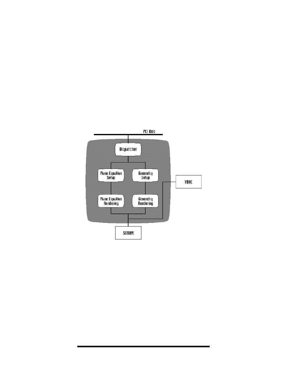
Figure 19:
Oxygen Chip Block Diagram
The Oxygen Chip block diagram (Figure 19) shows the components
and functions of the Oxygen chip. The
Dispatcher interfaces with the
PCI bus, using a built-in memory FIFO to transfer commands and data
from the computer’s main memory system to the graphics subsystem
for processing.
The data is then split into two paths and processed in parallel,
pipelined stages. Attribute information (i.e. color and transparency) is
calculated in the
Plane Equation path. Positional information
(i.e. which pixels should be lit) is calculated in the
Geometry path. Each
path does its work in two stages: Setup and Rendering. The Oxygen
chip processes three primitives at any given time: one in the
dispatcher, one in the setup stage, and one in the rendering stage.