Aiphone KAH-12 User Manual
Page 3
Attention! The text in this document has been recognized automatically. To view the original document, you can use the "Original mode".
IV-
8X5
1
:i::
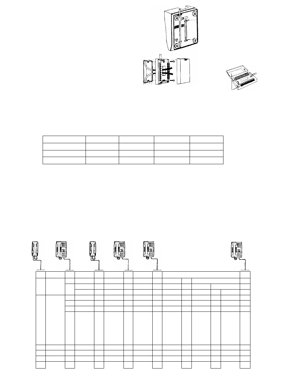
Please refer to the labels
on the sides of terminal
box and back of the cover.
INSTALLATION FOR WALL MOUNTING
1) Attach the mounting bracket to wall or plaster ring.
2) Remove the rubber feet from base of station.
3) To attach the provided handset cradle, remove two
screws, place the cradle and reinsert the two screws.
INSTALLATION OF TERMINAL BOX
1) Remove screws and cover as shown.
2) Attach bottom case to wall or 1-gang box.
3) Replace cover after wiring.
WIRING’
Use straight conductor cable. Do not use twisted pairs.
TERMINAL IDENTIFICATIONS
Lay out your system in advance. Determine the exact location of each station. We recommend a full complement
of wire be installed, even though you may not initially be installing the maximum number of stations available to your
system. This way, should you decide to add a station later, you can avoid running additional cables to existing stations.
Connect wires to terminals 01 & 02 if wire distance exceeds 200m (600’) total or more than 13 stations are used in your
KAH system.
Refer to the chart below and select the proper wire gauge to meet your requirements.
AWG WIRE SIZE
24 AWG
22 AWG
20 AWG
18 AWG
DISTANCE
330'
550'
830'
1300'
DIAMETER OF WIRE
0.5 mm
0.65 mm
0.8 mm
1.0 mm
DISTANCE
120 m
200 m
300 m
500 m
Referring to the diagram which illustrates your system, write your color code in the space privided. Begin your
installation with station #1. Note the position of the C terminal at each station. Be sure you wire each station correctly.
After installing the second station we recommend that the power supply be connected to the + and — terminals on
a phone and that a test be made for calling and talking between the stations. As each additional station is installed retest
between each station. Unplug power supply while making wiring connections.
INTERMIXED KAH-12 SPEAKER PHONE AND KAH-2 TELEPHONE STATIONS
The telephone station KAH-2 can place a call to two other stations (or paging blocks) as selected upon installation,
and can receive a call from any speaker phone master station. For full information please refer to instruction sheet
packed with KAH-2.
KAH-2
KAH-12
KAH-2
KAH-12
KAH-12
KAH- 2
1 0
c0
10
1 1
7^
20
20
C0
1
2
30
1 0
(
^ 'i
30
40
701
T0
c0
C0
70
7^
60
c0
6
6
60
70
VT^
70^
c0
2_V)
■y0
8 0
9 0
100
110
120
1 0
8 0
90
100
110
120
20
7®
90
100
110
120
30
20
c0
70
9
0
100
110
120
4
0
0i
0
0,
0
0,
0
0,
0
70"
6, 0
0.^
oT^
Oz0
02
0
02 0
O
2
0
-i-0
TW
+0
7^
-0
_0
______
-0
_0
____
)
-0
_0
V,
___
/
-0
_0
KAH- 2
KAH-12
PS-12C or
PS-12S
POWER SUPPLY
DC-12V