Wiring diagram • mjs-1ad/a system, Mounting, Mj-ds – Aiphone MJ-1AD User Manual
Page 4: Mj-1ad
Attention! The text in this document has been recognized automatically. To view the original document, you can use the "Original mode".
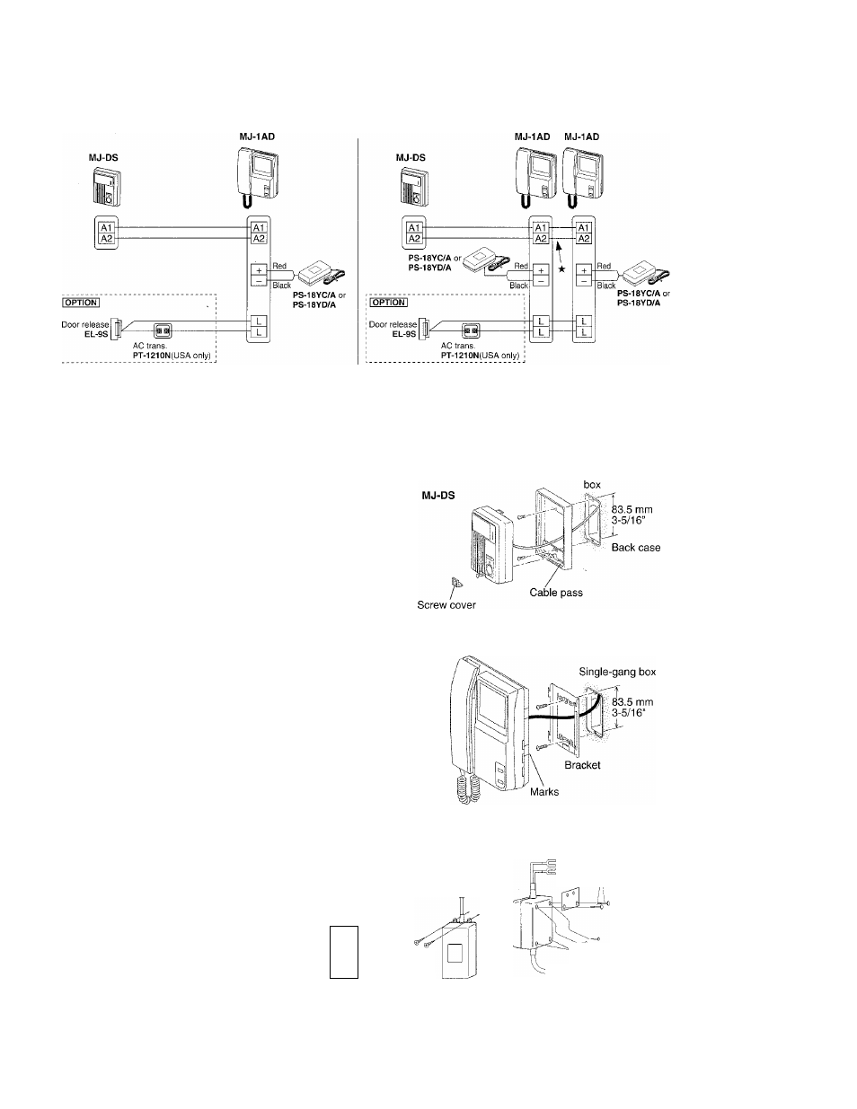
Wiring diagram
• MJS-1AD/A system
2 MJ-1AD monitor system
★ Strictly observe polarity.
MOUNTING
MJ-DS
The cover at the bottom conceals the mounting screw.
1. Loosen a screw at bottom of front panel. Lift it off
from back case to separate.
2. Mount back case to single-gang box at two points.
3. Connect 2 parallel wires on non-polar A1, A2.
4. Remount MJ-DS aligning on top, and fasten
bottom screw. Reattach the cover.
★ Do not apply any sealant around MJ-DS back
case, as openings are provided for evaporation.
Single-gang
MJ-1AD
Mounting bracket is attached on back of MJ-1 AD.
1. Attach the bracket to wall or single-gang box at two
points.
2. Connect 2 wires from MJ-DS on non-polar A1, A2.
3. Connect 2 wires from PS-18YC(D)/A to 18V DC
terminals. (Red: +, Black: -)
4. Mount MJ-1 AD onto the prongs of bracket, aligning
at marks. Pull it downward until it locks.
5. Plug in PS-18YC(D)/A power supply.
MJ-1 AD
PS-18YC/A( 120V AC), PS-18YD/A (220/240V
AC)
PS-18YC/A
Install the power supply within
1.9m, 6’3” of the monitor.
Do not attempt to extend the
Screw (
2
)
DC side of the power supply.
If necessary, extend the AC
side with an extension cord.
Bracket
(^0
Wood
screw (2)
PS-18YD/A
Screw (2)
(Supplied)
Bracket i
- Do not remove these
two screws