Speed connect^'^ drain, Troubleshooting guide, If you need to remove the stopper – American Standard 2506.011 User Manual
Page 5: Cable adjustment procedure, Fig. b.i fig. c
Attention! The text in this document has been recognized automatically. To view the original document, you can use the "Original mode".
Speed Connect^'^ Drain
Troubleshooting Guide
If sink does not hold water even though Stopper is in the "down” position:
• Follow CABLE ADJUSTMENT PROCEDURE.
If Stopper does not raise up fully or sink drains too slowly:
• Fallow CABLE ADJUSTMENT PROCEDURE.
If you need to remove the Stopper:
• Follow STOPPER REMOVAL PROCEDURE.
If you would like the ability to remove your Stopper simply by lifting it out of the drain:
• Follow STOPPER INSTALLATION PROCEDURE for
“Unlocked” mode.
CABLE ADJUSTMENT PROCEDURE
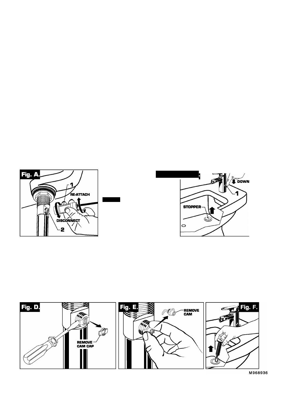
■ Disconnect the Cable from the Drain by threading the Cable Connector
11J
counter-clockwise.
Fig. A.
■ Look at the area on the Drain Body where the Cable was attached and locate the component labeled as
“Cam” in the illustration.
Fig. B.
■ Use a small screwdriver to rotate the Cam in the clockwise direction as far as it will go. At this point the
Stopper should be in the UP position.
Fig. B, C.
■ Push DDWN on the Lift-Knob to make sure it is fully down.
Fig. C.
■ Re-attach the Cable to the Drain Body Connection
(S)
by threading the Cable Connector
111
clockwise onto the
Drain Body Connection
(2)
and hand-tighten.
Fig. A.
Fig. B.I Fig. C
CAM
-CAM CAP
STOPPER REMOVAL PROCEOURE
■ Disconnect the Cable from the Drain by threading the Cable Connector
(11
counter-clockwise.
Fig. A.
■ Look at the area on the Drain Body where the Cable was attached and locate the component labeled
as “Cam” and “Cam Cap” in the illustration.
Fig. B.
■ Use fingers or small screwdriver under either side of the Cam Cap to pry it out from the Drain.
Fig. D.
■ Remove the Cam by pulling it straight out while wiggling gently to loosen the Rubber Seal.
Fig. E.
■ The Stopper can now be removed by lifting it out of the Drain.
Fig. F.