Wiring diagram, Specifications, 2) wall-mounting installation – Aiphone IE-2AD(U) User Manual
Page 3: If-da, Le-nc, Le-ja, Le-fy
Attention! The text in this document has been recognized automatically. To view the original document, you can use the "Original mode".
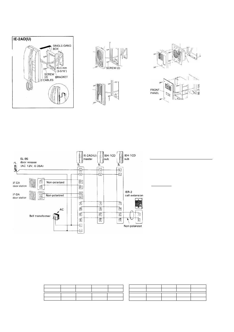
(2) Wall-mounting installation;
IF-DA
MAIN UNIT
SCREW
Surface mount
.
9 ^SINGLE-
GANG BOX
19
83.5 mm
(3-5/16")
BACK FRAME
lE-NC
MAIN UNIT
SCREW (2)
TERMINALS
J
Semi-flush mount
^ ^ SINGLE-
GANG BOX
Si
83.5 mm
(3-5/16")
SCREW (2) BRACKET
lE-JA
FRONT PANEL
Flush-mount
MAIN UNIT (p^2-GANG BOX
83.5 mm
(3-5/16")
SCREW (2)
TERMINALS
SCREW (2)
lE-FY
WOOD SCREW (2)
SCREW (4)
Flush-mount
*Master station; Attach the mounting bracket to wall or single-gang box with the supplied wood screws or screws. Insert the prongs of
the bracket into the holes of the body and pull the body downward. Be careful not to attach the bracket upside down.
* Door station; (*) When mounting IF-DA, lE-DC to wall directly, remove outlet part (*) on top or bottom of back frame to pass cable.
(**) Illustrates IF-DA's, and lE-DC mounts in the same manner.
WIRING DIAGRAM
Notes;
(1) Bell transformer for both communication
and door release; AC 12-16V, 450mA or
(
2
)
(3)
(4)
more (when EL-9S is used). AC 12-16V,
700mA or more (when door release of
other manufacture is used).
Door release; Use a door release EL-9S
(AC 12V, 350mA) or other manufacture’s
which does not exceed AC 12-16V 500mA,
when powered by a system’s bell
transformer.
Connect IER-2 to C, E terminals on any
room station convenient.
Locate a system’s power supply within a
lOm/33’ distance from main room station,
using 0.65 mm dia./22AWG wires.
2
SPECIFICATIONS
Power source: IE-2AD(U); Powered by a bell transformer AC 12-16V, 200mA OR a power supply DC 12-24V, 200my\.
Current consumption: Max. 200mA (AC 12-16V). Max. 200mA (DC 12-24V).
Calling: 4-stroke & 2-stroke electronic chime (w/slide volume switch).
Wiring: 2 wires (to door station) (non-polarized), 6 wires (between main/sub & sub room stations)
2 wires (to door release) (must be separated from communication's cable).
Door release button contact capacity: DC/AC 24V, 0.5A.
Wiring distance: ^Between IE-2AD(U) & door station;
AWG
24 AWG
22AWG
20AWG
18AWG
Distance
300’
500’
750'
1,180'
Diameter
0.5 mm
0.65 mm
0.8 mm
1.0 mm
Distance
90 m
150 m
230 m
360 m
AWG
24AWG
22AWC
20AWG
18 AWG
Distance
150'
250'
380'
590'
Diameter
0.5 mm
0.65 mill
0.8 mm
1.0 mm
Distance
45 m
75 m
115 m
180 m
Dimensions & weight: (H x W x D) 210 x 100 x 68 (mm); 8-1/4" x 3-15/16" x 2-11/16". Approx. 700 g (1.54 lbs.)
- 3 -