Wiring diagram – Aiphone DOOR STATION IC-DL1 User Manual
Page 3
Attention! The text in this document has been recognized automatically. To view the original document, you can use the "Original mode".
a
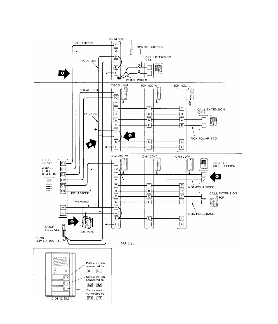
WIRING DIAGRAM
(1)
(2)
(3)
(4)
(5)
The above diagram illustrates IC-D3/IC-DL3 number button signals by
chime tone each floor separately.
Wiring is polarized between IC-D(L)l/2/3 door station and main
room station.
Wiring method remains unchanged on terminals [3 , GH ^nd [L], [L]
from door station to main room station, regardless of main room station
type, either IC-IAD(U), IC-1GD(U)/A or IC-2AD(U)/A.
Install a jumper wire between terminals [+] & on each main room
station, if door release is included.
The second door station is optional for IC-2AD(U)/A system. Select a
suitable type, either IC-Dl, IC-DLl or other IC series.
For power supply, use a bell transformer enough to supply power for
both communication and door release (EL-9S). See POWER SUPPLY
REQUIREMENTS on page 4.
- 3 -