Maintenance, System components, Installation – Aiphone IE-1AD(U) User Manual
Page 2: Y: s, Never
Attention! The text in this document has been recognized automatically. To view the original document, you can use the "Original mode".
BEFORE YOU INSTALL AND OPERATE THE EQUIPMENT
— Prohibitions and precautions —
Operation;
DO NOT HOLD HOOK SWITCH DOWN WHILE PICKING UP HANDSET. THE CHIME TONE
SOUNDS THROUGH THE HANDSET RECEIVER ELEMENT AND COULD CAUSE HEARING
DAMAGE.
Installation;
* DO NOT CONNECT ANY TERMINAL ON ANY UNIT TO AC POWER LINES.
When you mount lE-lAD(U) unit in place of existing bell or chime, be sure to disconnect wires
from the present transformer.
* BE SURE TO DISCONNECT WIRES FROM BELL TRANSFORMER (or POWER SUPPLY)
BEFORE YOU OPEN THE lE-lAD(U) UNIT OR MAKE WIRING CONNECTIONS.
* Avoid running the connecting wires through doors, windows or between furniture, which may pinch
and disconnect the wires.
* lE-lAD(U) equipment must be installed in as dry and dust-free environment as possible.
Maintenance;
* Clean your lE-lAD(U) equipment with a soft cloth dampened with neutral household cleanser. Never
use thinner, lacquer or benzine, etc.
* Do not splash water on the door station by hose, etc.
NEVER
NEVER
SYSTEM COMPONENTS
lE-FY
IE-1AD(U
lE-NC
lE-JA
IER-2
\
M
‘
.!
i
‘
y:
S
IE-DL3
EL-9S
Room station;
lE-lAD(U) ; Room master station. Wall-mount.
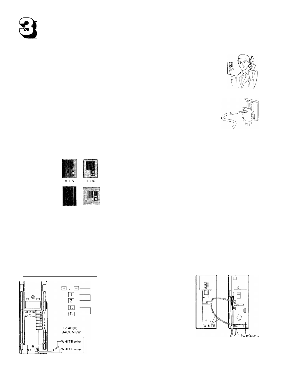
Door stations (one per system);
IF-DA : with brown plastic cover (surface-mount).
lE-DC ; - do - (surface-mount).
lE-NC : - do - (semi-flush mount).
lE-JA : with stainless steel cover (flush-mount).
lE-FY : with aluminum cover (flush-mount).
lE-DLl : 1-call, with brown anodized aluminum cover (surface-mount).
IE-DL2 : -do-2-call.
IE-DL3 : -do- 3-call (each with illumination lamp).
Options;
IER-2 : Call extension speaker, with volume control.
EL-9S ; Door release. AC 12V, 0.35A. Requires a separate bell transformer.
3
Notes; Your lE-lAD(U) can not work with IB/IC/ID series door stations. As to call extension, ICR-1 can be included in
lE-lAD(U) system.
INSTALLATION
[ (1) Actual terminal location;
CASE & CHASSIS INSIDE VIEW
For power supply.
Connect to door station (non-polarized).
For electric door release.
For cal! extension
(non-polarized)
(1) Remove 2 screws on back of the chassis and separate front case and chassis.
(2) As shown, take out two WHITE wires thru a hole on the chassis.
(3) Connect 2 wires to the wires from the IER-2 (non-polarized).
-
2
-