D. pilot – Bryant 376B User Manual
Page 8
Attention! The text in this document has been recognized automatically. To view the original document, you can use the "Original mode".
7. Remove eight screws that secure flue collector box to
center panel. Use care not to damage sealant.
8. Remove complete inducer assembly from furnace,
exposing flue openings.
9. Remove flue choke.
10. Using field-provided small wire brush, steel spring
cable, reversible electric drill, and vacuum cleaner;
clean cells.
a. Assemble wire brush and steel spring cable.
(1.) Use 4 feet of 1/4-in. diameter high-grade steel
spring cable (commonly known as drain
cleanout or Roto-Rooter cable).
(2.) Use 1/4-in. diameter wire brush (commonly
known as 25-caliber rifle cleaning brush).
NOTE:
The items called for in steps 1 and 2 can be pur
chased at a local hardware store.
(3.) Insert twisted wire end of brush into end of
spring cable, and crimp tight with crimping tool
or strike with baU-peen hammer. Tightness is
very important.
(4.) Remove metal screw fitting from wire brush to
allow insertion into cable.
b. Clean each heat exchanger cell.
(1.) Attach variable-speed reversible drill to end of
spring cable (end opposite brush).
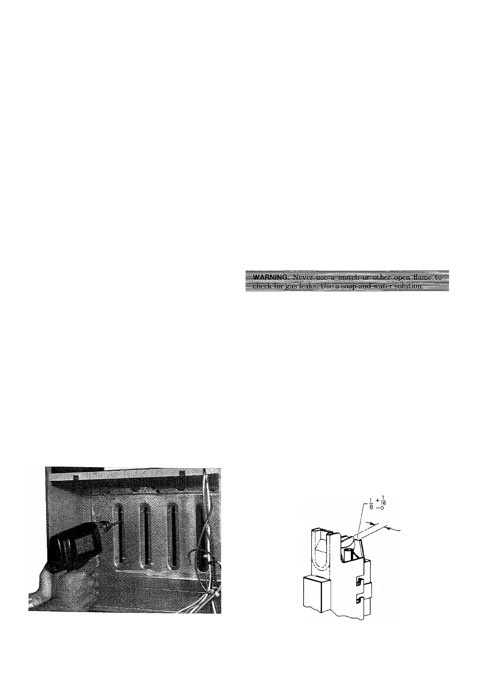
(2.) Insert brush end of cable into upper opening of
cell and slowly rotate with drill. Do not force
cable. Gradually insert at least 3 feet of cable
into two upper passes of cell. See Figure 18.
(3.) Work cable in and out of cell three of four times
to obtain sufficient cleaning. Do not pull cable
with great force. Reverse drill and gradually
work cable out.
(4.) Remove burner assembly and flame radiators.
(Identify gas valve leads.)
(5.) Insert brush end of cable in lower opening of
cell, and proceed to clean two lower passes of
cell in same manner as two upper passes.
(6.) Repeat the foregoing procedures until each cell
in furnace has been cleaned.
(7.) Using vacuum cleaner, remove residue from
each cell.
(8.) Using vacuum cleaner with soft brush attach
ment, clean burner assembly.
(9.) Reinstall flame radiators and burner assembly.
Care must be exercised to center the flame radi
ators in the cell openings. Refer to furnace wir
ing diagram when reconnecting gas valve leads.
11. After cleaning flue openings, check sealant on flue col
lector to ensure that it has not been damaged. If new
sealant is needed, contact your Distributor.
12. Reinstall flue choke. Be sure all screws are in place and
tight.
13. Clean and replace flue collector assembly, making sure
all eight screws are secure.
14. Replace four screws that secure the rehef box to blower
shelf.
15. Reconnect two wires to safeguard switch.
16. Reconnect wire harness edge connector to side of
inducer control box.
17. Reconnect vent pipe to relief box, reinstall pipe
enclosure.
18. Replace blower door only.
19. Turn on power and gas.
20. Set thermostat and check furnace for proper operation.
21. Check for gas leaks.
22. Replace control door.
D. Pilot
Check the pilot and clean if necessary at the beginning of
each heating season. The pilot flame should be high enough
for proper impingement of the safety element and to light
the burners. Remove the accumulation of soot and carbon
from the safety element or sensing probe. See Figure 19 and
check electrode position.
E. Electrica! Controls and Wiring
NOTE:
There may be more than one electrical supply to unit.
With power disconnected to unit, check all electrical connec
tions for tightness. Tighten aU screws on electrical connec
tions. If any smoky or burned connections are noticed, dis
assemble the connection, clean all parts and strip wire, and
reassemble properly and securely. Electrical controls are dif
ficult to check without proper instrumentation; therefore,
reconnect electrical power to unit and observe unit through
one complete operating cycle. If there are any discrepancies
in the operating cycle, contact your Dealer and request
service.
Figure 18—Cleaning Heat Exchanger Cell
A82181
^_T
16
Figure 19—Position of Electrode to Pilot
—8—