V. supply-air plenum installation (downflow), B. installation on a combustible floor – Bryant 376B User Manual
Page 2
Attention! The text in this document has been recognized automatically. To view the original document, you can use the "Original mode".
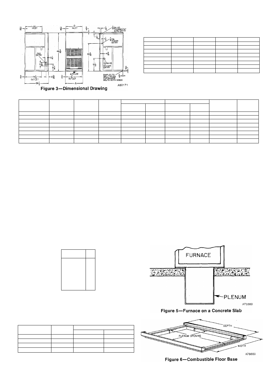
TABLE II—DIMENSIONS (In Inches)
Size
A
D
E
Vent Conn
024040
1 4-3/1 6
12-9/16
12-11/16
4
024055
14-3/1 6
12-9/16
12-11/16
4
036055
14-3/1 6
12-9/16
12-11/16
4
036075
17-1/2
1 5-7/8
16
4
048075
17-1/2
1 5-7/8
16
4
048095
17-1/2
1 5-7/8
16
4
060095
21
19-3/8
19-1/2
4
060115
24-1/2
22-13/16
23
5
TABLE III—RATINGS AND PERFORMANCE*
SIZE
Input
Buth*
Capacity
Buthtt
Temperature
Rise
Range
Heating
Cooling
Motor
HP & Type
Shipping
Weight
External Static
Pressure
Ft=/Min
External Static
Pressure
FCTMin
024040
48,000
39,000
50—80
0.10
610
0.5
Ш
1/5 Páó
130
024055
67,000
56,000
40—70
0.12
835t
0.5
890t
1/5 PSC
140
036055
67,000
56,000
35—65
0.12
1080
0.5
1157
1/3 PSC
142
036075
90,000
75,000
45—75
0.15
960t
0.5
1230t
1/3 PSC
160
048075
90,000
75,000
40—70
0.15
1240
0.5
1553
1/2 PSC
163
048095
114,000
95,000
55—85
0.20
1248
0.5 ■
1590
1/2 PSC
178
060095
114,000
95,000
55—85
0.20
1350
0.5
1929
1/2 PSC
188
060115
137,000
115,000
45—75
0.20
1037
0.5
2010
1/2 P$C
208
*The-above gas inputs are certified for altitudes to 2000 ft. For elevations above 2000 ft,
tDetermined by U.S. Government tests.
tTentative rating.
Installation comprises the following:
*1. Inspection
*11. Location, Ventilation, and Air for Combustion
*III. Gas Piping
*IV. Venting
V. Supply-Air Plenum Installation (Downflow)
VI. Attic Installation
VII. Crawl Space Installation
VIII. Filter Arrangement
IX. Sequence of Operation
X. Electrical Connections
XI. Startup and Adjustment
XII. Care and Maintenance
reduce.input 4% for each 1000 ft above sea level.
*To perform these sections (or installation steps), refer to
the appropriate sections of “Procedures for Induced-Com
bustion Gas-Fired Furnaces” booklet packaged with this
unit.
For accessory installation details, refer to applicable instal
lation literature.
V. SUPPLY-AIR PLENUM INSTALLATION (DOWNFLOW)
A. installation on a concrete slab
1. See Figure 3 for dimensions and location of supply-air
opening in furnace bottom.
2. Construct hole in floor per dimensions in Figure 4 and
Table IV.
3. Place plenum and furnace as shown in Figure 5.
B. Installation on a combustible floor
1. Read Installation Instructions packaged with combus
tible floor base.
HOLE IN
FLOOR
Ì
Figure 4—Floor Opening for Concrete Slab
TABLE IV—OPENING DIMENSIONS
Furnace Casing
Width
A
В
Heat-Oniy
Heat/Cooi*
14-3/16
13-1/8
19-5/8
20-15/16
17-1/2
16-7/16
19-5/8
20-15/16
21
1 9-7/8
19-5/8
20-15/16
24-1/2
23-7/16
19-5/8
20-15/16
*These dimensions apply when a Model 518A Evaporator Coil casing
is to be installed.
—2-