C. blower control center, Xi. startup and adjustment, B. automatic gas control valve – Bryant 376B User Manual
Page 6
Attention! The text in this document has been recognized automatically. To view the original document, you can use the "Original mode".
room temperature. Any hole in the plaster or panel through
which the wires pass from the thermostat should be ade
quately sealed with suitable material to prevent drafts from
affecting the thermostat.
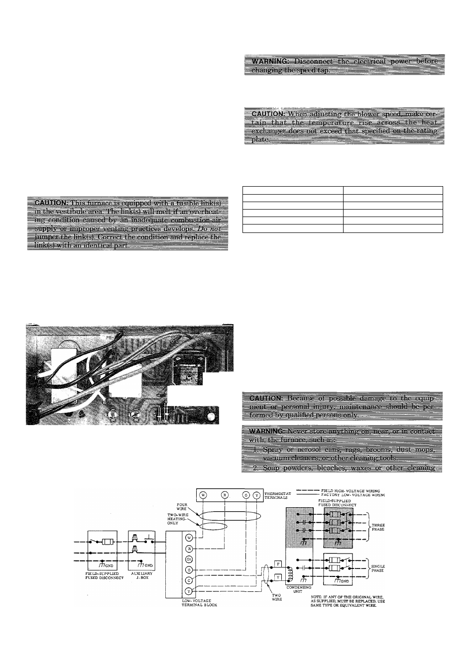
C. Blower Control Center
Each furnace features a blower control center. This will aid
the installer and serviceperson when installing and servic
ing the unit. A low-voltage terminal board is marked for
easy connection of field wiring. See Figure 14.
XI. STARTUP AND ADJUSTMENT
In addition to the following information, refer to “Proce
dures for Induced-Combustion Gas-Fired Furnaces” pack
aged with the unit.
NOTE:
The furnace blower door must be in place to complete
the 115-volt circuit to the furnace.
A. Adjustment of Blower Speed
To change motor speed taps, remove the motor tap lead. See
Table VI. and relocate it on the desired terminal on the
plug-in terminal block/speed selector located on the blower.
TABLE VI—SPEED SELECTOR
Speed
Tap No.
Common
C
Hi
1
Med-Hi
2
Med-Low
3
Low
4
The gas service pressure must not exceed 14 in. wc (8.1
ounces) for natural gas.
NOTE;
The gas valve regulator has been factory-set at 3.5
in. wc for natural gas. Refer to “Procedure for Induced-
Combustion Gas-Fired Furnaces” for readjusting when
checking input.
yii
- Ì-
Figure 14—Blower Control Center
B. Automatic Gas Control Valve
These units are equipped with an automatic gas control
valve. If not already checked when lighting the main
burner, check the proper operation of this valve by moving
the room thermostat pointer above and below room temper
ature and observing that the main burners light on “call for
heat” (there will be a time delay) and go off when the pointer
is moving below room temperature setting.
NOTE:
For ease of adjusting the pilot flame, disconnect and
tape one power lead at the main gas valve. Disconnect ter
minal No. 1. This will pervent main burner ignition and
allow time to adjust the pilot. Reconnect the power lead
after adjustment.
XII. CARE AND MAINTENANCE
- FIELD LOW-VOLTAGE WIRING
Figure 15—Heating and Cooling Application Wiring Diagram
a
7S46
i
—6—