Viii. filter arrangement – Bryant 376B User Manual
Page 4
Attention! The text in this document has been recognized automatically. To view the original document, you can use the "Original mode".
above the louvered control panel. Extend the sheet metal
shield over the furnace top far enough to cover the gas pipe
entry hole.
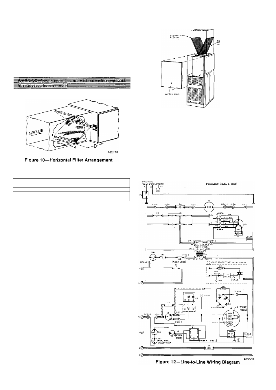
VIII. FILTER ARRANGEMENT
The two factory-supplied filters are shipped in the blower
compartment. After the return-air duct has been connected
to the furnace, install the filters in a V-formation inside the
return-air plenum. See Figure 10 and Table V for horizontal
applications. See Figure 11 for downflow applications.
TABLE V—FILTER RETAINER
Furnace Casing Width
0
1 4-3/1 6
15-3/16
17-1/2
14-1/2
21
13-9/16
24-1/2
12-1/4
LEGEND
lA-Transformer, 120-VAC/24-VAC
2D-Relay, Inducer Motor DPST-N. O.
2E-Relay, Heating Blower (HFR) SPST-N. C.
2F-Relay, Cooling Blower (CFR) DPDT
3A-Motor, Inducer
3D-Motor, Blower
4A-Capacitor, Run
5F-Valve, Gas (Redundant)
6C3-Lockout Module (When Used)
6F-Generator, Spark (Solid-State)
6H-Switch, Pilot-Flame Sensing SPOT
7H1-Switch, Limit SPST-N. C.
7H2-Switch, Draft Safeguard (SPST-N. C.) Manual-Reset
7H3-Switch, Auxiliary Limit (SPST-N. C.) Manual-Reset (When
Used)
7P-Pressure Switch-N.O.
7V-Switch, Flow Sensing SPOT
9G-Switch, Blower Door Interlock SPST-N. O.
10B1-Connector, Edge (Furnace Control Board)
10B2-Connector, Edge (Inducer Control Board-7 CKT)
10B3-Connector, Edge (Inducer Control Board-2 CKT)
10B4-Connector, Pilot
10B5-Factory Test Points
10B6-Connector, Blower Motor
11B-Fuse, In Line 2 Amp (When Used)
11C-Link, Fusible (Overtemperature)3 Required
11E-Ground, Equipment
TP-1-Test Point
0
Factory Wiring, 120-VAC
Factory Wiring, 24-VAC
Conductors on 6C1 (Furnace Control Board)
Conductors on 6C2 (Inducer Control Board)
Screw Terminal for Field Wiring
1/4-inch Quick-Connect Terminals
Figure 11—Position of Filters
IX. SEQUENCE OF OPERATION
Using the schematic wiring diagram, Figure 12, trace the
sequence of operation for the heating cycle is as follows;
1. When the blower door is in place, 120 volts is supplied
through blower door interlock switch 9G. Transformer
lA is energized, supplying 24 volts to heating-blower
relay coil 2E, which opens normally closed blower relay
contacts 2E in the low-speed circuit of blower motor
3D.
-4—