Bryant 376B User Manual
Page 5
Attention! The text in this document has been recognized automatically. To view the original document, you can use the "Original mode".
2. The wall thermostat “calls for heat,” closing the R and
W circuit. This closed circuit supplies power to the 24-
volt safety circuit containing Hmit switch 7H1, fusible
link lie, manual-reset draft-safeguard switch 7H2, and
manual reset auxiliary switch 7H3.
3. Simultaneously, the pick coil of gas valve 5F, spark
generator 6F, and inducer-motor relay coil 2D are ener
gized. Inducer-motor relay contacts 2D in the 120-volt
circuit close, starting inducer blower motor 3A. Also,
another set of contacts in inducer-motor relay 2D close
in the 24-volt circuit, and lock in inducer-motor relay
coil 2D. The coil is locked in until the R and W circuit
or safety circuit opens.
4. When the pick coil of gas valve 5F is .energized, gas
flows to the pilot. The pilot gas is ignited by a spark
produced by spark generator 6F. Simultaneously,
inducer motor 3A comes up to speed, actuating flow
sensing switch 7V, energizing the hold coil of gas valve
5F. The pick coil of gas valve 5F and spark generator
6F are deenergized when the contacts of pilot-flame
sensing switch 6H move from the normally closed posi
tion, breaking the circuit to the pick coil and spark gen
erator. In approximately 50 to 60 seconds, the nor
mally open pilot-flame sensing contacts close, making
the circuit to the MGV (Main Operator) of gas valve
5F. Gas valve 5F opens in approximately 10 seconds,
allowing gas flow to the main burners, which are
ignited by pilot 6H. Simultaneously, time-delay circuit
IIL in the blower control center is energized. Approxi
mately 50 seconds after gas valve 5F opens, heating
relay coil 2E is deenergized, which closes the 120-volt
contacts of heating relay 2E, starting blower motor 3D
on its heating speed.
5. When the thermostat is satisfied, the circuit between R
and W is broken, deenergizing gas valve 5F, inducer
motor relay 2D, and the solid-state time-delay circuit
on the printed-circuit board. The gas flow stops imme
diately to the pilot and main burners. After approxi
mately 105 seconds, heat relay 2E is energized and
blower motor 3D stops.
NOTE:
After a brief interruption of either electric or gas sup
ply, the furnace will not resume operation until the contacts
of pilot-flame sensing switch 6H move from the normally
open to the normally closed position.
Cooling Cycle
1. The wall thermostat “calls for cooling.”
2. The R, G, and Y circuits are energized. Simultaneously,
the R-and-Y circuit starts the outdoor condensing unit,
and the R-and-G circuit energizes cooling relay coil 2F,
which closes normally open contacts 2F, energizing the
cooling speed winding of motor 3D and opening the
normally closed contacts of cooling relay 2F.
X. ELECTRICAL CONNECTIONS
A. Line-Voltage Wiring
IMPORTANT: Before proceeding with the electrical con
nections, make certain that voltage, frequency, and phase
correspond to that specified on the unit rating plate. Also,
check to be sure that the service provided by the utility is
sufficient to handle the additional load imposed by this
equipment. Refer to the unit rating plate for equipment elec
trical requirements.
in accordance with the National Electrical Code and any
local codes or ordinances that might apply.
Use a separate fused branch electrical circuit containing a
properly sized fuse or HACR-type circuit breaker for this
furnace. A disconnecting means must be located within
sight of, and readily accessible to, the furnace. The blower
door switch may be acceptable in some areas as a discon
necting means.
If fine-voltage wiring to the unit is encased in a nonmetalfic
sheath, connect the incoming ground wire to the grounding
wire inside the furnace J-box. If metallic conduit is used, it
will serve as the ground.
B. Low-Voltage Wiring
Make field low-voltage connections at the low-voltage termi
nal strip. See Figure 15.
NOTE:
When the furnace is instedled in the horizontal posi
tion with RH discharge air, low-voltage wire connections
can be made easier by removing the two control box mount
ing screws and letting the control box turn so that the low-
voltage screw terminals are visible. Be sure to reinstall the
control box after the connections are made.
NOTE:
Use AWG No. 18 “color-coded” copper thermostat
wire for lengths up to 100 ft. Above 100 ft, use AWG No. 16
wire.
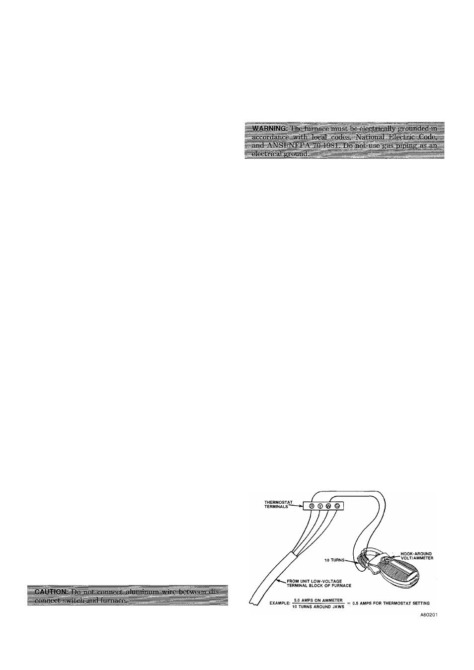
IMPORTANT:
The thermostat heat anticipation must be set
to match the amp draw of the gas valve and electrical com
ponents in the R-W circuit. Accurate amp draw readings
can be obtained at thermostat subbase terminals R & W.
Figure 13 illustrates an easy method of obtaining the actual
amp draw. The amp reading should be taken after the
blower motor has started.
The room thermostat should be located where it wfll be in
the natureJ circulation path of room air. Avoid locations
where the thermostat would be exposed to cold-air infiltra
tion, drafts from windows, doors, or other openings leading
to the outside, or exposed to air currents from warm- or
cold-air registers; or to exposure where the natural circula
tion of the air is cut off—such as behind doors, above or
below mantels, shelves, etc.
The thermostat should not be exposed to heat from nearby
fireplaces, radios, televisions, lamps, or rays from the sun.
Nor should the thermostat be mounted on a wall containing
pipes or warm-air ducts, or a flue or vent that could affect
its operation and prevent it from properly controlling the
See Figure 15 for wiring diagram showing the proper field
high- and low-voltage wiring. Make all electrical connections
Figure 13—Amp Draw Check With Ammeter
—5—