52c,p series, Open the control box, Remove the unit from the wall sleeve – Carrier P User Manual
Page 4
52C,P
SERIES
4
OPEN THE CONTROL BOX
The control box is factory wired. To open the box,
remove the 2 screws on the top of the control box and
lower the front hinged panel. See Figure 6.
REMOVE THE UNIT FROM THE
WALL SLEEVE
1. Remove the four mounting screws that secure the
PTAC unit to the wall sleeve (2 screws per side).
See Figure 7.
2. Grasp the sides of the unit and slide it from the
sleeve.
NOTE: The mounting screws may be in a different
location depending on brand of wall sleeve
attached.
The chassis weighs between 110 and 150 lbs. Take
proper safety precautions to avoid personal injury
when lifting and moving the chassis.
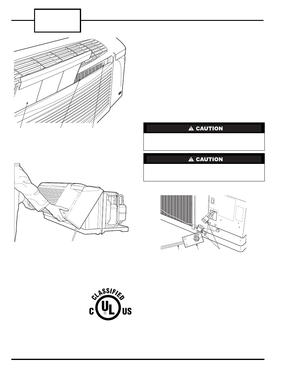
The unit basepan may have water in it. Tilt the
unit back slightly when removing it from the sleeve
to drain some of the water into the sleeve.
CONDUIT
ACCESS
PANEL
MOLEX
PLUGS
FIGURE 5 — PLUG ASSEMBLY ON
HARDWIRE UNITS
REMOVABLE
FILTER
LOCATION OF
REMOVED FILTER
LOCKING SCREW
(NOTE: 2nd LOCKING SCREW
IS LOCATED BEHIND
2nd FILTER)
FIGURE 3 — LOCATION OF LOCKING SCREWS
BEHIND FILTERS
FIGURE 4 — REMOVING FRONT PANEL
Replacement Package Terminal Air Conditioner,
CLASSIFIED BY UNDERWRITERS LABORATO-
RIES INC., AS TO ELECTRIC SHOCK, FIRE AND
CASUALTY HAZARDS ONLY. FOR FIELD INSTAL-
LATION WITH EXISTING WALL SLEEVES, OUT-
DOOR, LOUVERS, AND INDOOR PANELS AS
SPECIFIED ON THE PRODUCT.