Unit disassembly, Tools needed, Remove front panel – Carrier P User Manual
Page 3: Disconnect power for cord-connected unit
3
UNIT DISASSEMBLY
This section includes common procedures for disas-
sembly and re-assembly of unit.
TOOLS NEEDED
The following field-supplied items are recommended
for general disassembly of the unit:
• Flat head screw driver
•
5
/
16
-in. nut driver
• Safety glasses
• Needle nose pliers
REMOVE FRONT PANEL
NOTE: Before removing front panel, remove 2 locking
screws (if installed) located behind the filter handles.
See Figure 3. If a lateral duct accessory is installed, the
plenum must be removed before removing the front
panel. Refer to Remove Lateral Duct Extension section
for removal instructions.
1. Grasp the front firmly near bottom of both sides.
2. Pull the panel forward then upward to release
magnetic latches and partition hooks. See Figure 4.
DISCONNECT POWER FOR
CORD-CONNECTED UNIT
1. Turn selector switch to OFF position.
2. Open the disconnect switch at main power supply.
Use proper Lockout and Tag procedures.
3. Unplug the unit service cord.
DISCONNECT POWER FOR
PERMANENTLY CONNECTED
(HARDWIRED) UNITS
1. Turn selector switch to OFF position.
2. Open the disconnect switch at main power supply.
Use proper Lockout and Tag procedures.
3. Remove screw from access cover and remove
access cover.
4. Pull out the plug assembly and disconnect. See
Figure 5.
IMPORTANT: Follow manufacturer’s instruc-
tions when disassembling and re-assembling a
unit for cleaning, maintenance, or part replace-
ment. When disassembling wiring, it is strongly
recommended that numbered stickers be
attached to identify leads and terminals to aid in
the re-assembly process. Always review safety
procedures prior to the start of a job.
Prior to servicing electrical equipment, discon-
nect all power to avoid electric shock! Tag all dis-
connects. Never alter cord or plug and do not use
extension cords.
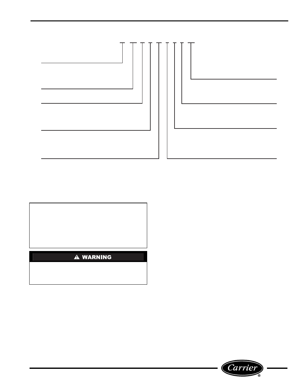
Electrical Data
3 – 230/208-v, 60 Hz
4 – 265-v, 60 Hz
Cooling Capacity (nominal)
07 – 7,000 Btuh
09 – 9,000 Btuh
12 – 12,000 Btuh
15 – 15,000 Btuh
52 PQ A 3 12 3 0 1 AA
Series Designation
PTAC (Packaged Terminal Air Conditioner)
Non-Performance
Changes 0-9
Chassis Options
Blank or AA – Standard
CP – Corrosion Protection
RC – Wall Thermostat Control
RP – Wall Thermostat Control with
Corrosion Protection
CE – Cooling with Electric Heat
CQ – Heat Pump with Electric Heat
PC – Cooling Only
PE – Cooling with Electric Heat
PQ – Heat Pump with Electric Heat
Packaging
1 – Domestic
Latest Revision
A – Z
Electric Heater Size
0 – No Heating (Cooling Only Model)
2 – 2.3 kW
3 – 3.4 kW
5 – 5.0 kW
FIGURE 2 — MODEL NUMBER NOMENCLATURE