Carrier P User Manual
Page 27
27
4. Remove the thermostat capillary from the outdoor
coil and clip any wire ties holding the capillary in
place.
5. Disconnect the wires and carefully remove the
thermostat and capillary from the unit, noting
location of wires for easy re-assembly.
6. Reverse Steps 1-5 to reinstall.
■
CAPACITOR
—
To remove the capacitor, perform
the following steps:
1. Turn off unit power as described in UNIT
DISASSEMBLY section.
2. Open the control box as detailed in the UNIT
DISASSEMBLY section of this manual.
3. Properly discharge the capacitor as described in
the Capacitor section under Component Opera-
tion and Troubleshooting.
4. Remove the leads to the capacitor. Note the wire
locations to ease re-assembly.
5. Remove the screw holding the capacitor.
6. Remove capacitor.
7. Reverse Steps 1-6 to reinstall.
■
FAN CYCLE SWITCH — The fan cycle switch is
located on the front of the control box. To remove the
fan cycle switch, perform the following steps:
1. Turn off unit power as described in UNIT
DISASSEMBLY section.
2. Open the control box as described in UNIT
DISASSEMBLY section of this manual.
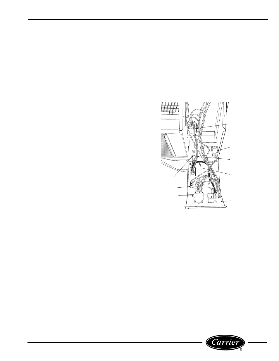
3. Remove the 3 wires from the fan cycle switch. See
Figure 52 for location, noting location of wires for
re-assembly.
4. Push the snaps of the switch housing toward the
switch with a pair of pliers or small screwdriver.
Gently push the switch out of the housing.
5. Reverse Steps 1-4 to reinstall.
■
SELECTOR SWITCH — To remove the selector
switch from the unit, perform the following steps:
1. Turn off unit power as described in UNIT
DISASSEMBLY section.
2. Remove selector switch knob. See Figure 51.
3. Open control box as described in the UNIT
DISASSEMBLY section of this manual.
4. Remove all the wires to the selector switch. Label
wires to simplify re-assembly. See Figure 52.
5. Remove the 2 screws mounting the switch and
remove switch.
6. Reverse Steps 1-5 to reinstall.
PLAIN WIRE (L1)
TO ROTARY SWITCH
GROUND SCREW
FAN CYCLE
SWITCH
INDOOR
THERMOSTAT
SELECTOR
SWITCH
CAPACITOR
OUTDOOR FROST
THERMOSTAT
RIBBED WIRE (L2)
TO CAPACITOR (C)
POWER CORD
POWER CORD
FIGURE 52 — COMPONENT LOCATIONS
IN OPEN CONTROL BOX