3) wall mounting, Semi-flush mounting (to new and plastered wall), Gang box requirements – Aiphone IE VIDEO DOOR STATION MF-D User Manual
Page 3: Semi-flush mounting (in existing constructions), 4) directory card replacement, Wiring diagram
Attention! The text in this document has been recognized automatically. To view the original document, you can use the "Original mode".
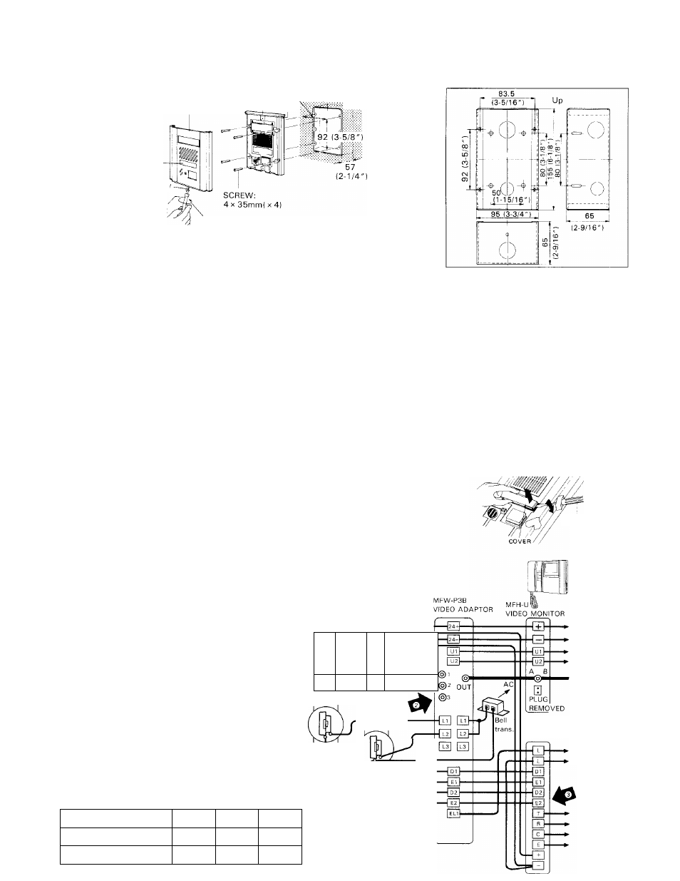
(3) WALL MOUNTING
SEMI-FLUSH
MOUNTING
(to new and plastered wall);
MAIN UNIT
FRONT PANEL
83.5 3-GANG BOX(w/mud ring)
(3-5/16") (as specified)
RIB
MCW-V DIMENSIONS;
DIRECTORY CARD
OVAL HEAD SCREW
DRIVER
FASTEN
Loosen the oval head screw on bottom front panel by the provided driver.
Pull the front panel at bottom and remove from the main unit.
Connect wires on terminals on back of the main unit.
Mount the main unit on the electrical box with supplied four screws (4 mm 0 x 35 mm).
Attach the front panel to the main unit inserting to the rib provided on top main unit.
Rescrew the special screw on bottom front panel by the provided driver.
GANG BOX REQUIREMENTS;
MF-D can be mounted on the 3-GANG BOX as specified below;
For North America; * 3-GANG BOX, 1-5/8" DEEP, WITH RAISED COVER, NEMA standards
* 3-GANG BOX, SHALLOW, Tile Wall Box 1/2" knockouts, NEMA standards
For everywhere except N. America; * JIS 3-SWITCH BOX (w/mud ring) (Model: DS4913, to be supplied
by AlPHONE).
SEMI-FLUSH MOUNTING (in existing constructions);
To mount MF-D on existing wall or on marble wall (where no plaster is used), use Aiphone’s MCW-V box, without mud ring.
Cut out a hole in the wall, of W:95 mmx H:155 mm (W: 3-3/4" x H:6-l/8"), securing depth of 65 mm (2-9/16").
SURFACE-MOUNTING;
Aiphone supplies MCW-R box, designed for MF-D surface-mounting. For details, refer
to the Instructions packed with MCW-R box.
(4) DIRECTORY CARD REPLACEMENT
The six directory cards are supplied with the MF-D unit. When replacing the card,
first remove front panel and the card cover can be removed, using a screwdriver.
a
WIRING DIAGRAM
PS-24N
POWER
SUPPLY
MFW-P3
IE-2AD(U)/MF-D VIDEO SYSTEM;
Connect power supply PS-24N to MFW-P3/P3B
& IE main room station individually.
Door (i)
MF-D
Door \2)
MF-D
MFW-CZ video camera installation is optional
(for surveillance of 3rd entry/area).
3^ When lE-lAD(U) or lE-lGD(U) main room
stations are used, there are no
H
•11
A1
EL-9S ®
D2
terminals and only one MF-D video door station
can be connected.
For wiring connections on MFW-P3/P3B, be sure that
door station and door release terminals collate with one
another in the following manner;
Coaxial cable terminals
1
2
3
Door station terminals
Dl, El
D2, E2
D3, E3
Door release terminals
LI
L2
L3
D3
EL-9S @
[I>
- 3
SCREWDRIVER
To; next MFH-U
IE-2AD(U)
MAIN ROOM STATION
To; IEH-1CD
Sub room station