Never, Iimstallatioim, Installation location – Aiphone IE VIDEO DOOR STATION MF-D User Manual
Page 2: Installation height, Maintenance, 1) acutal terminal location, 2) coaxial cable connection, Y/////a, Installation, Terminals (on mfw-p3/p3b)(non-polarized)
Attention! The text in this document has been recognized automatically. To view the original document, you can use the "Original mode".
BEFORE
YOU
INSTALL
AND
OPERATE
THE
EQUIPMENT
- Prohibitions and precautions -
NEVER
STREET
LIGHT
IIMSTALLATIOIM
©DO NOT CONNECT ANY TERMINAL TO AC POWER LINES.
When you mount MF-D in place of existing bell or chime, be sure to disconnect wires from the
present transformer.
@ DO NOT OPEN THE MF-D UNIT, WITHOUT FIRST REMOVING PLUG OF POWER SUPPLY
FROM AC OUTLET.
@ Do not drop or hit the MF-D which may damage the CCD camera unit.
©Avoid running the connecting wires through doors, windows or between
furniture, which may pinch and disconnect the wires.
INSTALLATION LOCATION
® Select the MF-D installation location, observing the following con
ditions.
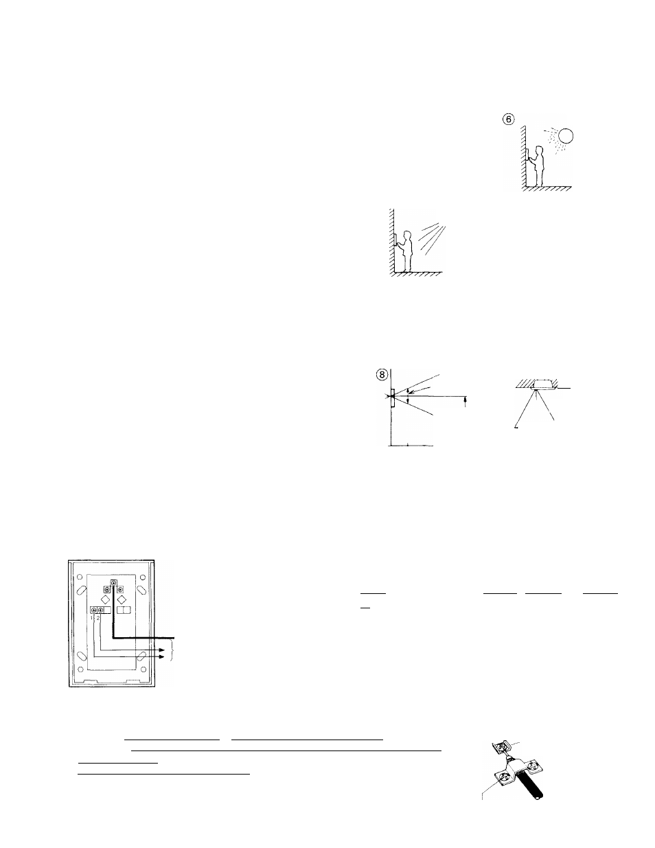
® Avoid installing the MF-D in a location that would be exposed to;
* direct sunlight, * temperature/humidity extremes, * water, * oil,
* dust, * iron dust, * inflammable and chemical products, etc., or
* where the strong light source is behind the person standing at the
door station. The face will apear dark on the room station monitor.
This situation can occur when buildings create shadows on entry
areas.
@ As shown, it is recommended that the MF-D be installed at an en
trance not exposed to direct sunlight and with 200 to 300 lux secured
on the object.
INSTALLATION HEIGHT
©Taking the adults’ average height into consideration, decide a most
suitable height of MF-D door station.
It is suggested that the center of a camera lens be installed
at an adults’ average height minus 10cm(4").
MAINTENANCE
@ Clean your MF-D unit with a soft cloth dampened with neutral house
hold cleanser. Never use lacquer thinner or benzine, etc.
)Do not splash water directly on unit.
NEVER
@
NORTH
WEST
MF-D
©NTRANCE
EAST
SOUTH
IDIM
BRIGHT
NEVER
NORTH
ENTRANCE
WEST ^ MF-D EAST
SOUTH
Approx. 500 mm
(19-5/8")
Average adults'
height minus
100 mm (4")
i
500 mm (19-5/8")
y/////A
©
500 mm
(19-5/8")
Approx. 760 mm (30")
INSTALLATION
(1) ACUTAL TERMINAL LOCATION
COAXIAL CABLE: Connect to 1, 2, 3 on MFW-P3/P3I
I 1 1 I Connect to either |Pl| |E1|, |D2| |E2| or |P3| |E3|
i
2
j I
’ terminals (on MFW-P3/P3B)(non-polarized).
COAXIAL CABLE |
2 wires
1
to: MFW-P3/P3B adaptor
FOLD BACK
MF-D BACK VIEW
(2) COAXIAL CABLE CONNECTION
11 I
P
1 1 mm (7/1 6")
3 mm (1/8")
8.5 mm (3/8")
Use 3C-2V or 3C-2V OR RG-59/U which must meet the following specifications;
* [Both core and braided conductors must be of copper (not of copper-weld)|
* Impedance: 75 ohm. __________________________
* [^rmittcd closed loop DC resistance: 7 ohnu]
* Permitted attenuation: 6 dB at 4 MHz.
* Cable sheath size should not exceed 7.4 mm (5/16").
When using 3C-2V, strip the insulation and fold back the braided conductors, as shown
to avoid shorting to core conductors.
-
2
-
Type; 5C-2V
Type: 3C-2V
Connect core
conductor to terminal
Connect braided conductors
with clamp