High temperature shutdown, Field boost, Over voltage proteqion – Generac Power Systems Air-cooled Industrial Mobile Generator 09843-2 User Manual
Page 10: Engine governed speed, High oil temperature shutdown, Over voltage protection
Attention! The text in this document has been recognized automatically. To view the original document, you can use the "Original mode".
Generac IM-72LP Industrial Mobile Generator
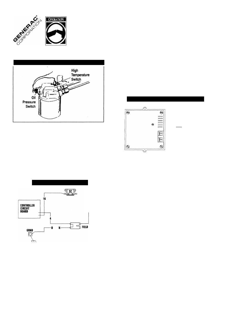
Figure 5 — Oil Pressure and Temperature Switches
HIGH TEMPERATURE SHUTDOWN
Temperature switch (Figure 5) with normally-open (N.O.) con
tacts is mounted on the engine. Should engine temperature
exceed about 284°
F
(140°C), the switch contacts close and
the engine shuts down.
FIELD BOOST
The controller Circuit Board houses a field boost diode and
resistor. These two components are part of a “field boost” cir
cuit (Figure 6).
Figure 6 — Field Boost Circuit
CLOSEST TO
BEARING
During engine cranking only, a positive DC (battery) voltage
is delivered through the diode, resistor, brushes
and
slip rings,
and to the generator rotor. Application of this voltage to the
rotor Hashes the field” whenever it is started. Flashing of the
field each time the generator starts makes sure that a suffi
ciently strong magnetic field is available to produce the required
“pick up” voltage in the stator windings.
OVER VOLTAGE PROTEQION
A solid state voltage regulator (Figure 7) controls the gener
ators AC output voltage. This regulator supplies an excitation
current to the rotor. By regulating the rotor’s excitation cur
rent, the strength of its magnetic field is regulated and, in
turn, the voltage delivered to connected electrical loads is
controlled. When the AC frequency is 60 Hz, voltage is reg
ulated at 120 volts (voltage-to-frequency ratio is 2-to-1).
Figure 7 — Solid State Voltage Regulator
^^[¿"Zh-SENSIIIG
CZ3=^4(+K TO BOTOI
i=3=-i{-b-^(iiœCT CURRENT)
---- ЬЕЙВИ STATOR
— E X C I T A T I O N WniOING
(ALTERNATING CURRENT)
The voltage regulator also incorporates a “voltage surge pro
tection circuit.” This circuit prevents troublesome surges in the
generator AC output voltage. Voltage surge is a common
cause of damage to electronic equipment.
ENGINE GOVERNED SPEED
The generator is equipped with a 2-pole revolving field (rotor)
which must be driven at 3600 rpm to produce the unit’s rated
AC frequency of 60 Hz. The gas engine governor was factory
set to about 62 Hz (2900 RPM) at no-load. After installing it,
the technician should check and adjust the governed speed.
Setting no-load frequency slightly high helps prevent exces
sive frequency, rpm and voltage droop under heavy electrical
loading.
DANGER: DO NOT TAMPER WITH THE ENGINE GOV
ERNOR SETTINGS. EXCESSIVELY HIGH ENGINE
SPEEDS ARE DANGEROUS AND INCREASE THE
RISK OF PERSONAL INJURY AND DAMAGE TO
EQUIPMENT AND/OR PROPERTY. EXCESSIVELY
LOW SPEEDS IMPOSE A HEAVY LOAD ON THE
ENGINE WHEN ADEQUATE ENGINE POWER IS NOT
AVAILABLE AND MAY SHORTEN ENGINE LIFE. THE
GENERATOR SUPPLIES CORRECT RATED FRE
QUENCY AND VOLTAGE ONLY AT THE PROPER
SPEED. SOME ELECTRICAL DEVICES MAY BE DAM
AGED BY INCORRECT FREQUENCY AND/OR
VOLTAGE. IF ENGINE SPEED APPEARS TO BE
INCORRECT, CONTACT YOUR NEAREST AUTHO
RIZED SERVICE FACILITY.
i n d u s t r i a l M o b i l e G e n e r a t o r
10