Additional information, Additional information -11 – Generac Power Systems Air-cooled Recreational Vehicle Generator 9734-3 User Manual
Page 10
Attention! The text in this document has been recognized automatically. To view the original document, you can use the "Original mode".
Generac NP-66LPG Recreational Vehicle Generator
ADDITIONAL INFORMATION
This section discusses some of the engine protective devices,
overload protection and breaking in a new generator.
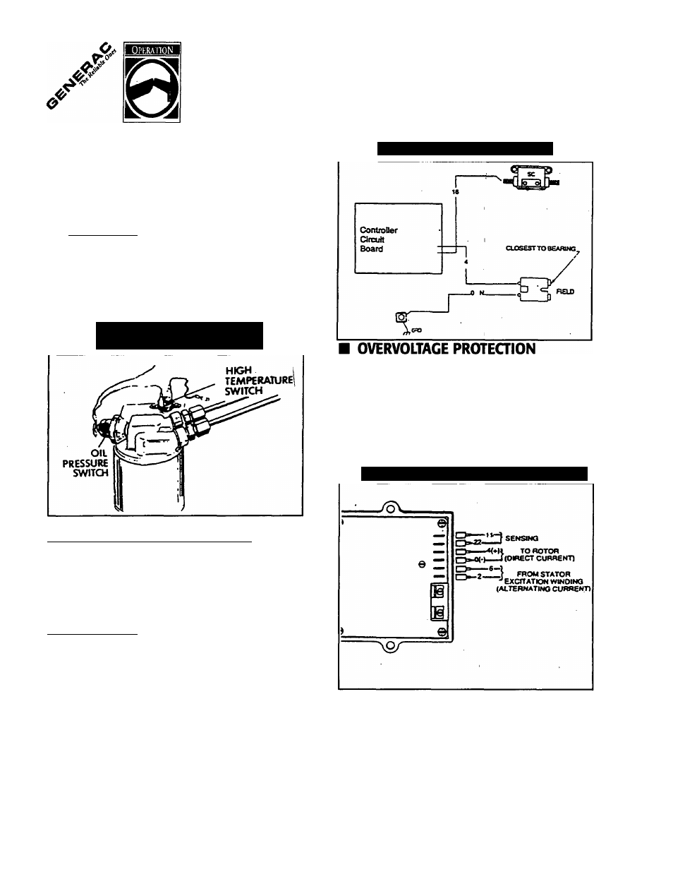
■ AUTOMATIC LOW OIL PRESSURE
SHUTDOWN________________________________
The engine is equipped with a normally-open (N.O.) oil
pressure switch (Figure 4). Engine oil pressure holds the
switch open during cranking and operation. Should oil pres
sure drop below about 8-10 PSI, the switch contacts close
and the engine automatically shuts down.
Figure 4 — Switches for Engine
Safety Shutdown
Figure 5 — Field Boost Circuit
■ HIGH TEMPERATURE SHUTDOWN
An oil temperature switch (Figure 4) with normally-open (N.O.)
contacts is mounted near the oil filter. If oil temperature were
to exceed about 284®F (140°C), the switch contacts close
and the engine shuts down.
■ FIELD BOOST_______________________________
The Controller Circuit Board houses a field boost diode and
resistor which are not part of the automatic choke circuit.
These two components are part of a “field boosf circuit (Rgure
5). During engine cranking only, a positive DC (battery) volt
age is delivered through the diode, resistor, brushes and slip
rings, and the generator rotor. Application of this voltage to
the rotor “flashes the field” whenever it is started. Hashing of
the field each time the generator starts makes sure that a suf
ficiently strong magnetic field is available to produce “pick up”
voltage in the stator windings.
A solid state voltage regulator (Figure 6) controls the gener
ator’s AC output voltage. This regulator supplies an excitation
current to the rotor. By regulating the rotor’s excitation current,
the strength of its magnetic field is regulated and, in turn, the
voltage delivered to connected electrical loads is controlled.
When the AC frequency is 50 Hz, voltage is regulated at 120
volts (voltage-to-frequency ratio is 2-to-1).
Figure 6 — Solid State Voltage Regulator
The voltage regulator also incorporates a “voltage surge pro
tection circuit.” This circuit prevents troublesome surges in the
generator AC output voltage. Voltage surge is a common
cause of damage to electronic equipment.
R e c r e a t i o n a l V e h i c l e G e n e r a t o r
10