To remove belt guard (see fig. 24), To replace ground drive belt (se figs. 24 and 25), Ground drive belt adjustment (se fig. 25) – Poulan PPRT5C User Manual
Page 16: Service, Adjustments
Attention! The text in this document has been recognized automatically. To view the original document, you can use the "Original mode".
service
and
adjustments
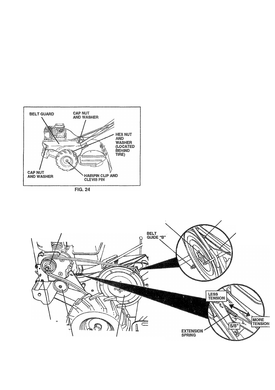
TO REMOVE BELT GUARD (See Fig. 24)
NOTE; For ease of removal, remove hairpin dip and clevis
pin from left wheel. Pull wheel out from tiller about 1 inch
(2.5 cm).
» Remove two (2) cap nuts and washers from side of belt
guard.
® Remove hex nut and washerfrom bottom of belt guard
(located behind wheel).
® Puli belt guard out and away from unit.
Replace belt guard by reversing above procedure.
TO REPLACE GROUND DRIVE BELT (Se
Figs. 24 and 25)
® Move left wheel and remove belt guard as described
“TO REMOVE BELT GUARD”.
•
Loosen belt guides “A” and “B” and also nuts “C” ar
“D”.
•
Remove old belt by slipping from engine pulley first
® Place new belt in groove of transmission pulley ar
into engine pulley. BELT MUST BE IN GROOVE O
TOP OF IDLER PULLEY. NOTE POSITION OF BEl
TO GUIDES.
•
Tighten belt guides “A” and “B” and nuts “C” and “D
•
Check belt adjustment as described below.
•
Replace belt guard.
•
Reposition wheel and replace clevis pin and hairp
clip.
GROUND DRIVE BELT ADJUSTMENT (Se
Fig. 25)
For proper belt tension, the extension spring should ha\
about 5/8 inch (16 mm) stretch when drive control bar is
“ENGAGED” position. This tension can be attained t
follows:
•
Loosen cable clip screw securing the drive contr
cable.
•
Slide cable forward for less tension and rearward fi
more tension until about 5/8 inch stretch is obtains
while the drive control bar is engaged.
•
Tighten cable clip screw securely.
BELT
GUIDE “A”
ENGINE
PULLEY
CABLE CLIP
SCREW
NUT “C”
DRIVE
CONTROL
CABLE
NUT “D
IDLER
PULLEY
TRANSMISSION
PULLEY
FIG. 25
16