Engine throttle lever, Keyswitch starter, Engine controls – Troy-Bilt 12204-10HP User Manual
Page 15
Attention! The text in this document has been recognized automatically. To view the original document, you can use the "Original mode".
Section 3: Features and Controls
Д WARNING
The tiller handlebars can be swung out
30° to the right side for use only with the
PTO Chipper/Shredder attachment. This
is done by loosening the mounting bolt
on the handlebar base. Never operate
your tiller or attachments, other than the
PTO Chipper/Shredder, with the handle
bars in the right side position. Doing so
could result in unsafe handling and
personal injury.
Engine Throttle Lever
Use the throttle lever (G, Figure 3-1) to
adjust engine speed as well as to start
and stop the engine.
Move the lever away from the STOP
position before starting the engine.
Engine speeds are variable and range
between the FAST and SLOW. Use the
STOP position to turn the engine off.
NOTE: A secondary throttle lever is
located on the front of the
8
HP and 10HP
engines. A separate On/Off switch may
also be available on the engine. (See
Engine Owner’s Manual for information.)
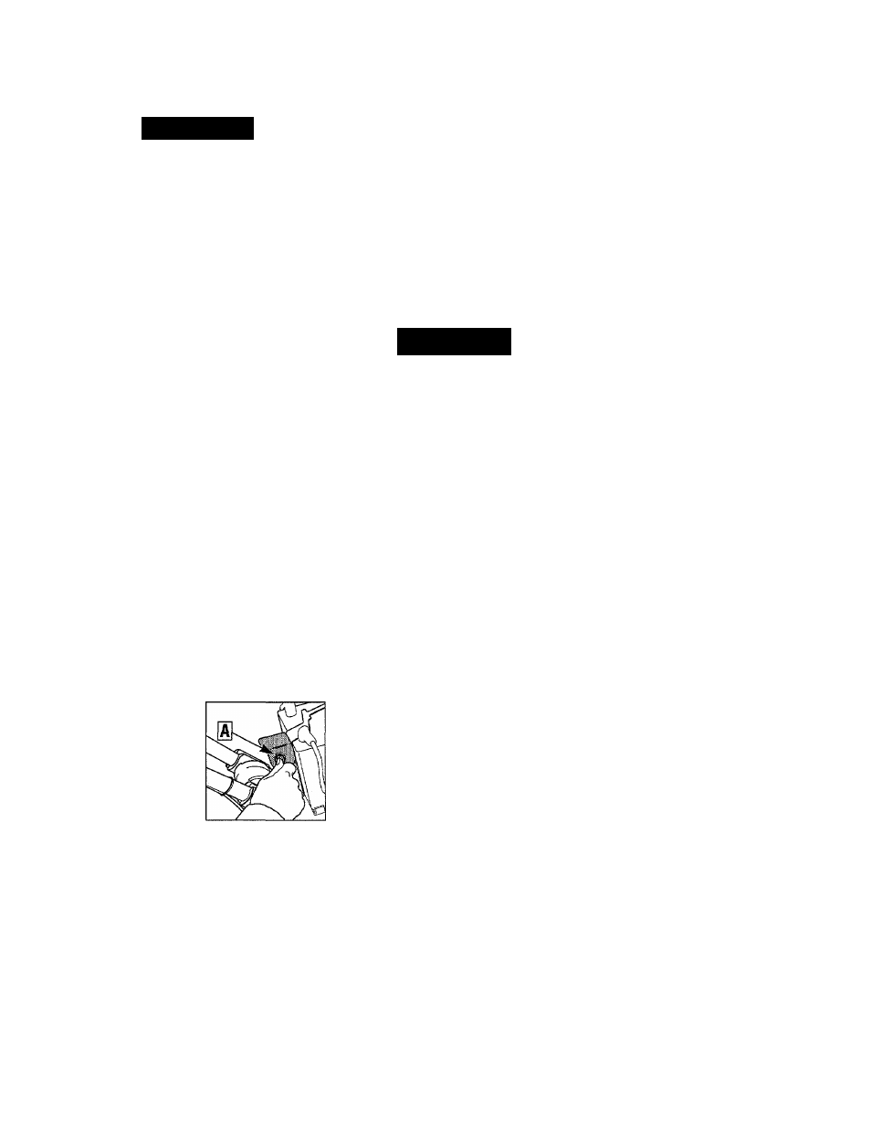
Keyswitch Starter
The keyswitch starter on electric start
models (A, Figure 3-5) has three
positions: OFF, RUN and START. Turn
the key to START to start the engine.
Release the key and
it will return to the
RUN position. Turn
the key to OFF to
stop the engine.
(Another way to
stop the engine is to
move the engine
throttle lever to the
STOP position.)
Engine Controls
Refer to the engine manufacturer’s Engine
Owner’s Manual (included in the tiller lit
erature package) to identify the controls
on your engine.
IMPORTANT:
An engine On/Off switch, a
secondary throttle control, a choke lever
and a fuel line shut-off control may be
located on the engine. Refer to your
Engine Owner’s Manual for detailed
information.
A
WARNING
To avoid serious personal injury or
damage to equipment, do not start your
engine at this time. Complete starting
instructions are described in Section 4,
Operation.
Figure 3-5
15