Controller cables, Controller cables -12, P/i-ap55t user’s manual – Asus P/I-AP55T User Manual
Page 80
Attention! The text in this document has been recognized automatically. To view the original document, you can use the "Original mode".
P/I-AP55T User’s Manual
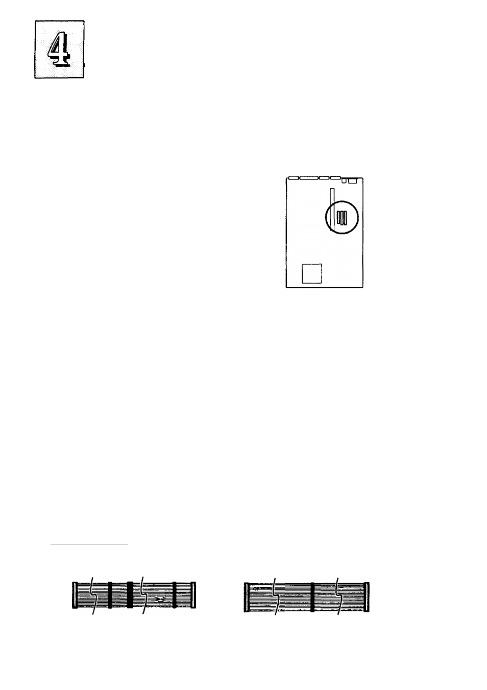
I/O Port Connectors
Pini is the upper left-hand pin on each connector
Floppy Disk Drive
cable connector
IDE Hard Disk Drive
cable connectors.
Primary IDE (Middle)
Secondary IDE (Right)
W hen you connect a ribbon cable to any of these I/O connectors, you
must orient the cable connector so that the Pin 1 edge of the cable is at
the Pin 1 end of the on-board connector. The Pin 1 edge of the ribbon
cable is colored to indentify it
Controller Cables
The mainboard comes with the following cables:
• 11DE ribbon connector cables
• 1 floppy disk drive ribbon connector cable
Connector Cables
Floppy Drive ribbon cable
IDE ribbon cable
4-12
- P5B Premium Vista Edition (188 pages)
- P5B (140 pages)
- P5B (56 pages)
- M2N68-CM (28 pages)
- P5KPL-VM/1394/SI (94 pages)
- P5GD1-VM (92 pages)
- P5AD2-E Premium (2 pages)
- P5GD1-VM (88 pages)
- P5AD2 Premium (8 pages)
- DELUXE A7N8X-E (114 pages)
- P5KPL-AM SE (40 pages)
- P5KPL-AM SE (38 pages)
- P5KPL-AM SE (62 pages)
- P4S8X-X (64 pages)
- P5K-VM (98 pages)
- K8V-X SE (82 pages)
- M2N68-AM SE2 (40 pages)
- P4P800 SE (125 pages)
- P4P800 SE (16 pages)
- DELUXE SERIES M3A32-MVP (176 pages)
- P5AD2 Deluxe (148 pages)
- M4A79 Deluxe (122 pages)
- A7V266-E (108 pages)
- Application Manual (11 pages)
- Application Manual (10 pages)
- Application Manual (4 pages)
- Application Manual (8 pages)
- Application Manual (2 pages)
- Application Manual (6 pages)
- Application Manual (9 pages)
- Application Manual (3 pages)
- Application Manual (1 page)
- Application Manual (5 pages)
- M4A88T-I DELUXE (70 pages)
- M4A88T-I DELUXE (44 pages)
- P9X79 DELUXE (2 pages)
- RAMPAGE IV GENE (1 page)
- P9X79 (156 pages)
- P8H61-M PLUS V3 (64 pages)
- A85XM-A (78 pages)
- M4A78L-M LE (64 pages)
- M2N68-AM (96 pages)
- M2N68-AM (62 pages)
- M2N68-AM (38 pages)
- Blitz Formula (3 pages)