Discharge chute control rod assembly, Discharge chute control rod – Troy-Bilt 42000 User Manual
Page 9
Attention! The text in this document has been recognized automatically. To view the original document, you can use the "Original mode".
Section 2: Assembly (continued)
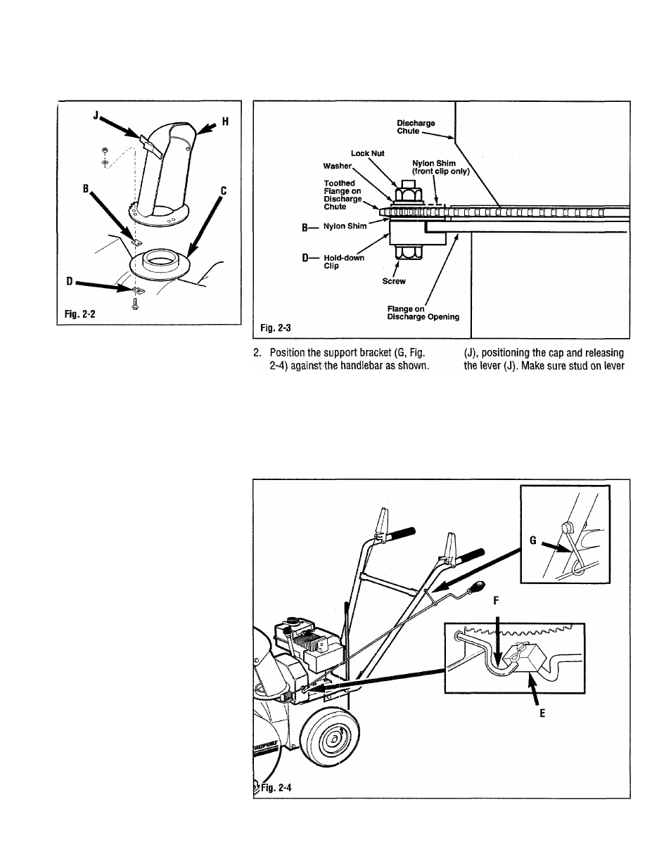
4. Position the discharge chute onto the
discharge chute flange on the auger
housing, with the front hold-down clip
(Fig. 2-3) hooked under the flange,
and the nylon shim on top of the
hold-down clip against the top of the
toothed flange.
5. Rotate the discharge chute opening
so it is facing to the right. Install the
nylon shim (B, Fig. 2-2) and hold
down clip (D) on the left side of the
chute as shown in Fig. 2-3.
5. Rotate the discharge chute opening
so it is facing to the left. Install the
nylon shim (B, Fig. 2-2) and hold
down clip (D) on the right side of the
chute as shown in Fig. 2-3.
IMPORTANT: Engine oil must be added
to the engine crankcase before the
engine is started. Seethe engine
owner manual (included with this unit)
for more specific engine oil information.
Discharge chute control rod
assembly
1. Position the hole in the swivel block
(E, Fig. 2-4) over the hooked end of
the chute control connecting rod (F).
Secure the swivel block to the
connecting rod with a cotter pin.
Bend the ends of the cotter pin over
to secure it in place.
3.
Using two 7/16” wrenches, secure the
support bracket (G) to the handlebar
with one 1/4-20 x 1-1/2 cap bolt, one
1/4 flat washer and one 1/4”-20
locknut.
Move the discharge deflector cap (H,
Fig. 2-2) upward by pulling out lever
is seated in one of the positioning
holes on the discharge chute cap.