F, figs. 3-1 & 3-3—gear shift iever, H, fig. 3-1—skid shoes, J, fig. 3-4—scraper blade – Troy-Bilt 42000 User Manual
Page 13: Engine controls, K, fig. 3-1—ignition key, L, fig. 3-1—throttle
Attention! The text in this document has been recognized automatically. To view the original document, you can use the "Original mode".
Section 3: Controls (continued)
usually be adjusted to a low angle,
especially in windy conditions.
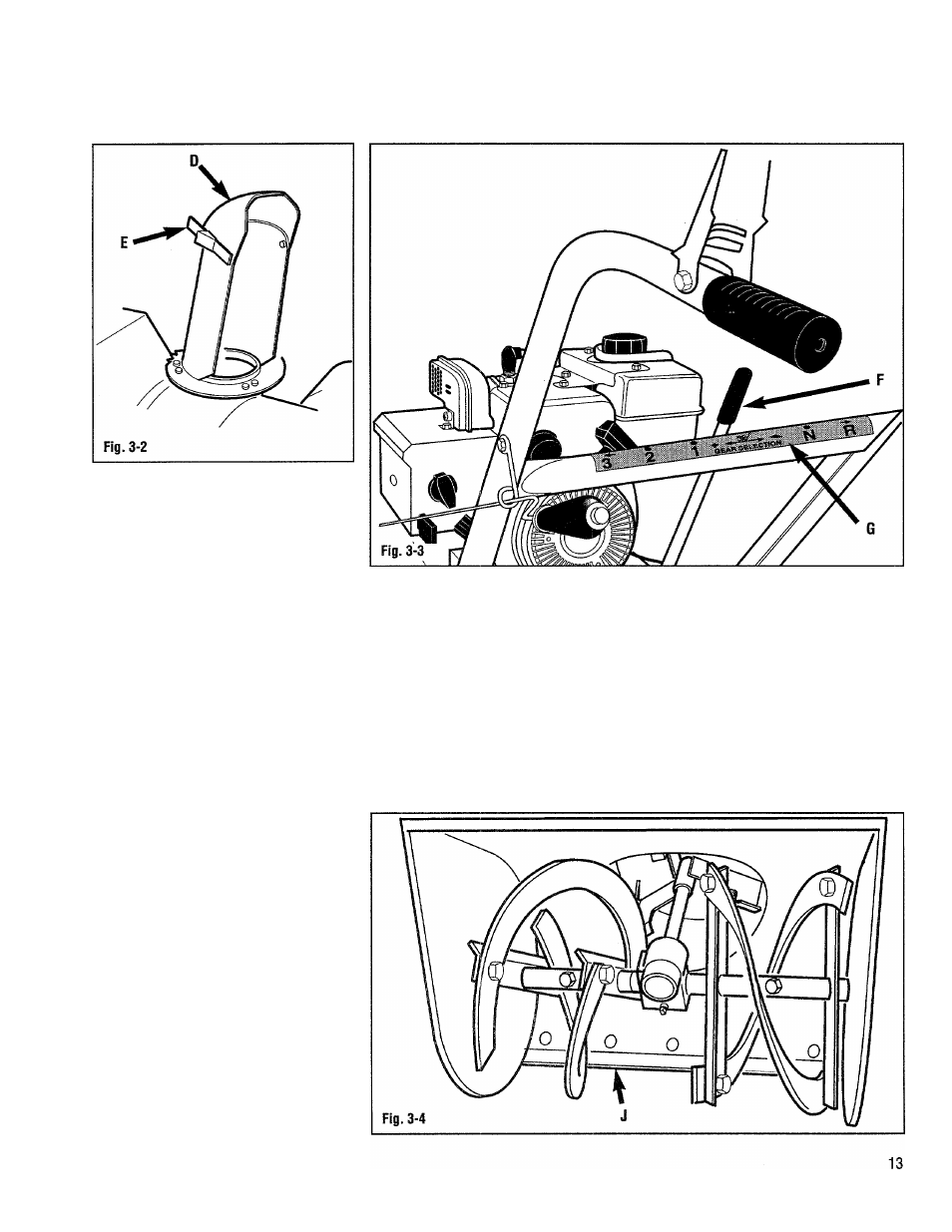
F, Figs. 3-1 & 3-3—Gear shift
iever
Controls the selection of travel speeds:
' three forward, one neutral, and one
reverse. The gear shift decai (G, Fig. 3-3)
indicates the gear shift lever positions for
the various travel speed settings.
H, Fig. 3-1—Skid shoes
Control the distance between the auger
housing and the ground. This distance
should be adjusted to clear any uneven or
gravel surfaces. Refer to the following
section, “Operation”, for proper skid shoe
adjustment information.
J, Fig. 3-4—Scraper blade
Designed to contact the ground to clear
snow down to the pavement. Refer to the
following section, “Operation”, for proper
adjustment information.
ENGINE CONTROLS
K, Fig. 3-1—Ignition key
* This key has two positions: “S” and
STOP Rotating the key into the “S”
position activates the engine ignition and
allow the engine to be started. Rotating
the key into the STOP position stops the
engine. Always remove the ignition key
from the ignition whenever the unit is not
in use.
L, Fig. 3-1—Throttle
Controls the speed of the engine. Always
run the engine at full throttle (the “i»”
position).
Note: the engine lubrication and cooling
systems operate best at full throttle.
Operating the engine at less than full
throttle for extended periods can reduce
the performance of this system.