Wheel drive belt replacement, Auger drive cable adjustment – Troy-Bilt 42000 User Manual
Page 25
Attention! The text in this document has been recognized automatically. To view the original document, you can use the "Original mode".
Section 5: Maintenance (continued)
Wheel drive belt replacement
REMOVAL:
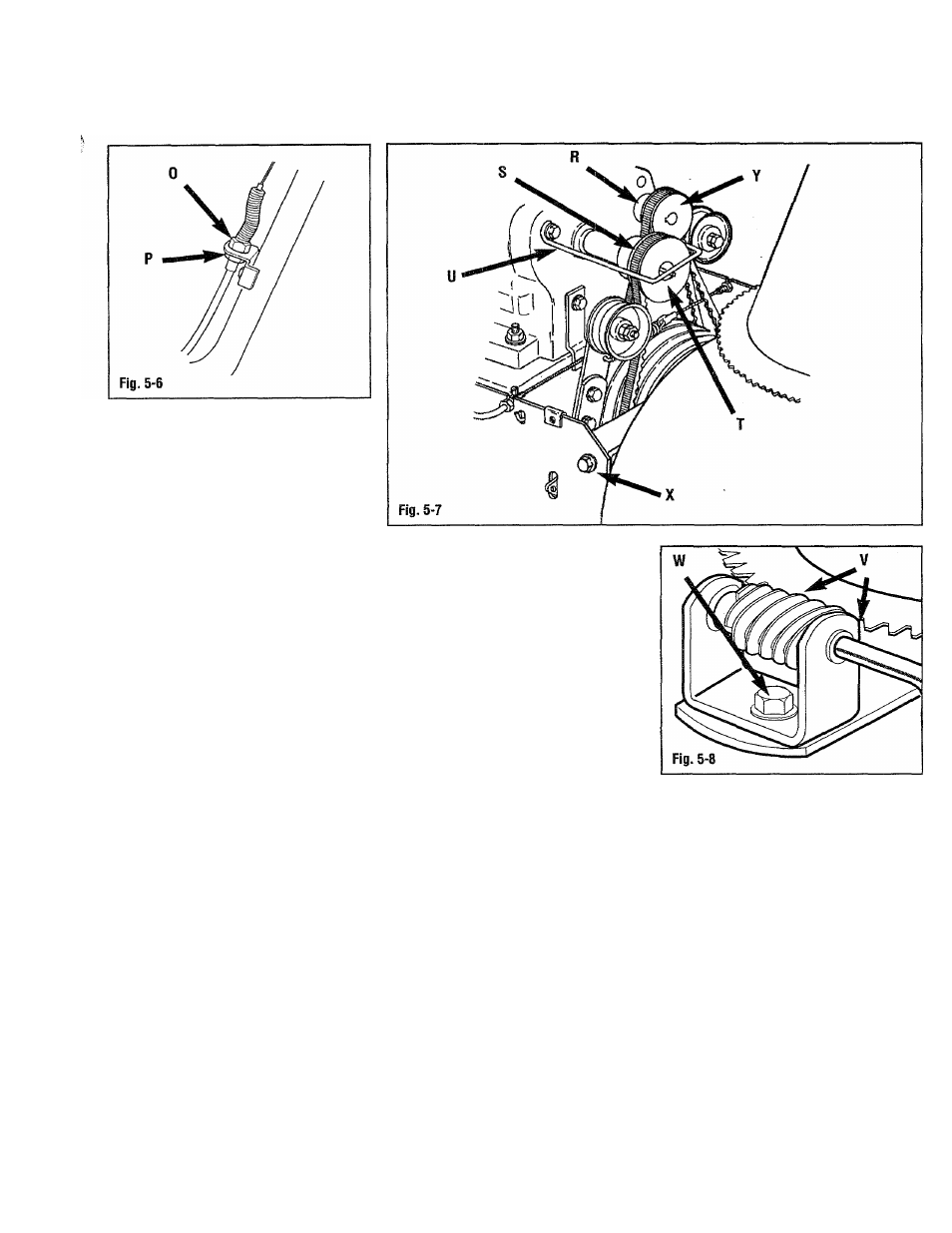
1. Remove the two bolts securing the
belt cover (G, Fig. 5-4. Remove the
belt cover (G).
2. Remove bolt (W, Fig. 5-8) securing
the worm gear and support (W) to the
unit. Remove the worm gear and
support (W).
3. Remove the four flange screws (X,
Fig. 5-7) securing the auger housing
and the frame/handlebar assembly
together.
4. Carefully separate the auger housing
from the frame/handlebar assembly..
Remove the auger drive belt (S) from
the drive pulley on the engine (T).
Loosen any belt guides (U), if
necessary to remove belt (S) from
pulley (T). Prop the handlebars on a
solid, stable object, such as a
workbench.
5. Remove the wheel drive belt (R).
Loosen any belt guides, if needed, to
remove belt (R).
INSTALLATION:
1. Position the wheel drive belt (R),
around the transmission pulley and
the drive pulley (Y) on the engine.
2. Adjust and tighten any belt guides
loosened earlier during step 5,
“REMOVAL”. Adjust the belt guides
1/16” (1mm) away from the wheel
drive belt (R) when the belt is tight.
3. Move the auger housing and the
frame/handlebar assembly together
and position the auger drive belt (S)
around the drive pulley on the engine
(T).
4. Secure the auger housing and the
frame/handlebar assembly together
with the four flange screws (X)
removed earlier.
5. Adjust and tighten any belt guides (U)
loosened earlier during step 4,
“REMOVAL”. Adjust the belt guides
1/16” (1mm) away from the auger
drive belt (S) when the belt is tight.
6. Position the worm gear and support
(V, Fig. 5-8) back in place on the unit.
Secure the worm gear and support
with bolt (W).
7. Rotate the chute control crank and
check for binding. Reposition the
worm gear and support (V), as
needed, for smooth operation.
8. Adjust the wheel drive cable as
instructed earlier in this section.
9. Position the belt cover (G, Fig. 5-4)
back on the unit and secure with the
two bolts removed earlier.
Auger drive cable adjustment
1. Remove the two bolts securing the
belt cover (G, Fig. 5-4. Remove the
belt cover (G).
25