3 controls, A, fig. 3-1—auger drive control lever, B, fig. 3-1—wheel drive control lever – Troy-Bilt 42000 User Manual
Page 12: C, fig. 3-1- control rod, D, figs. 3-1 & 3-2—discharge chute deflector cap, Auger drive control lever, Wheel drive control lever
Attention! The text in this document has been recognized automatically. To view the original document, you can use the "Original mode".
Section
3 Controls
This section defines the various controls
on the unit. Refer to the following section,
“Operation”, for an explanation of the
proper use of these controls.
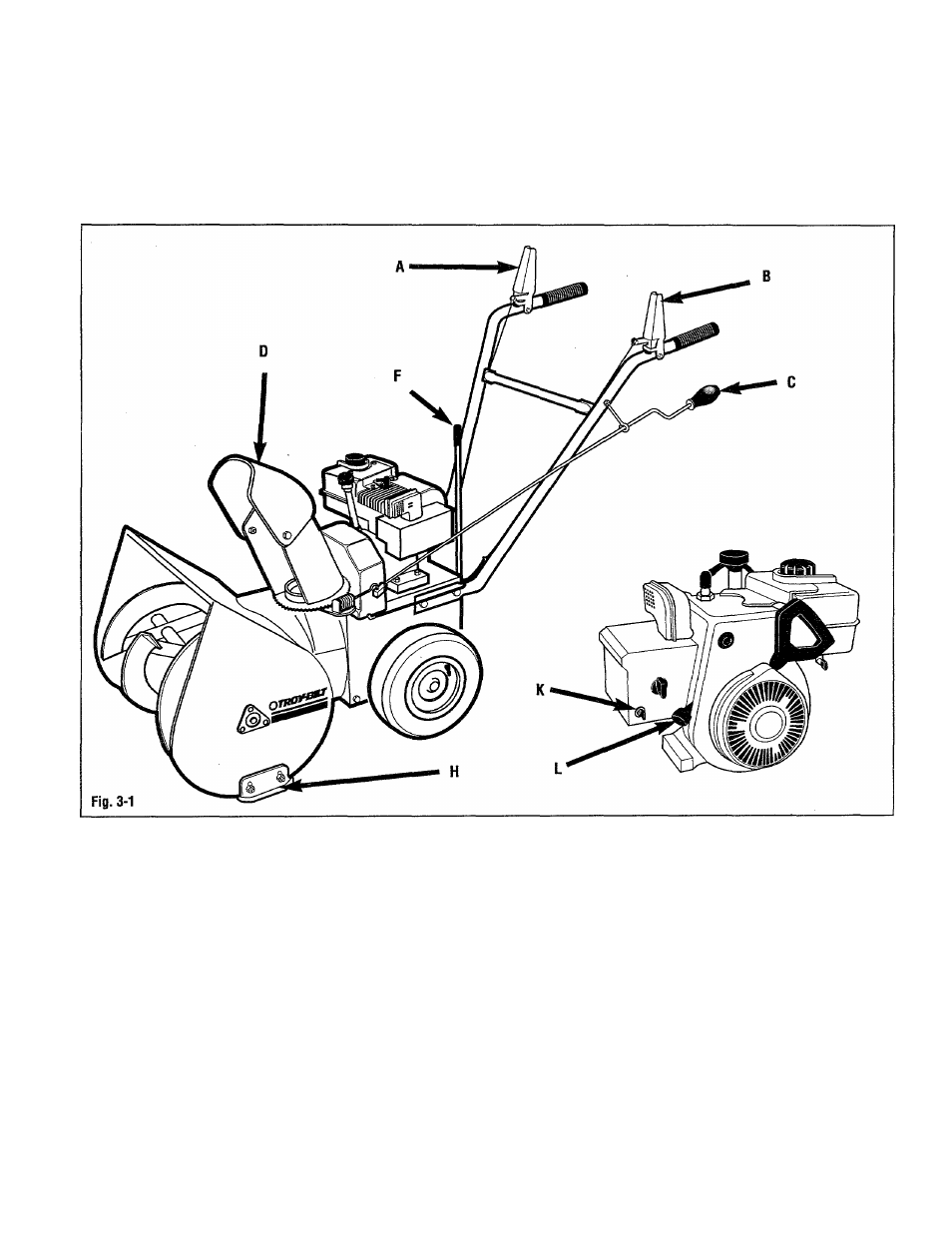
A, Fig. 3-1—Auger drive control
lever
Control s the engagement of the auger
drive. When this lever is down against the
handlebar and the engine is running, the
auger will rotate.
B, Fig. 3-1—Wheel drive control
lever
Control s the engagement of the wheel
drive. When this lever is down against the
handlebar and the engine is running, the
wheels will rotate.
C, Fig. 3-1-
control rod
-Discharge chute
Controls the direction the discharge chute
is facing. Rotate this crank clockwise to
turn the discharge to the right; rotate
counter-clockwise to turn
the discharge chute to the left.
Approximately 8 turns of this crank will
move the discharge chute all the way
from one side to the other.
D, Figs. 3-1 & 3-2—Discharge
chute deflector cap
The angle of the discharge chute deflector
cap controls the vertical angle of the
snow discharge. Lift lever (E, Fig. 3-2) to
adjust discharge chute deflector cap
angle (make sure stud on lever is seated
in one of the positioning holes on the
discharge chute cap (D) after adjusting).
The discharge chute deflector cap should
12