Chute control crank assembly, Control lever cable assembly, Assembly (continued) – Troy-Bilt 42000 User Manual
Page 10
Attention! The text in this document has been recognized automatically. To view the original document, you can use the "Original mode".
Section
2
:
Assembly (continued)
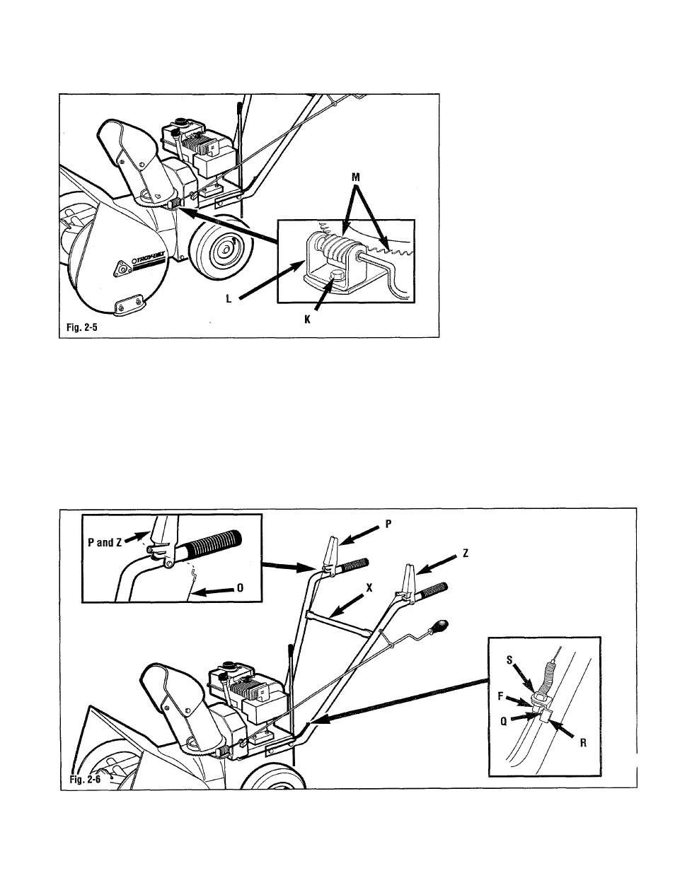
Chute control crank assembly
1. Cut the tie securing the chute control
crank bracket (L, Fig. 2-5). Remove
the locknut backing screw (K).
2. Position the chute control crank
bracket (L) on the auger housing so
the worm gear meshes with the teeth
in the discharge chute flange.
3. Secure the chute control crank
bracket the to auger housing with the
locknut removed in step 1.
4. Rotate the chute control crank and
check for binding. Adjust, if required,
as follows:
a. Loosen the nut backing bolt (K, Fig.
2-5).,
b. Adjust bracket (L)-(push in to
tighten: pull out to loosen).
c. Retighten the nut backing bolt (K).
d. Check chute rotation and repeat
adjustment as needed.
,5. Apply multi-purpose grease to the
worm gear and toothed edge of
discharge chute flange (M).
Control lever cable assembly
1. Hook the control cable assembly (0,
Fig. 2-6) entering the left side of the
frame into the right control lever (P).
The control cable (0) must be routed
behind cross-member (X).
2. Hook the control cable assembly (0)
entering the right side of the frame
into the left control lever (P and Z).
Control cable (0) must be routed
behind cross-member (X).
10