5l maintenance, A warning, Maintenance schedule – Troy-Bilt PONY E666M User Manual
Page 17
Attention! The text in this document has been recognized automatically. To view the original document, you can use the "Original mode".
Section
5l Maintenance
A
WARNING
Before
inspecting,
cieaning
or
servicing the machine, shut off engine,
wait for aii moving parts to come to a
compiete stop, disconnect spark plug
wire and move wire away from spark
plug. Remove ignition key on electric
start models.
Failure to follow these instructions can
result in serious personal injury or prop
erty damage.
TILLER LUBRICATION
MAINTENANCE SCHEDULE
PROCEDURE
NOTES
Check motor oil ievel
2 , 3
Clean engine
2 , 7
Check drive belt tension
1,4
Check nuts and bolts
1,4
Change motor oil
1,4,6
Lubricate tiller
4
Service foam pre-cleaner air filter
(If so equipped)
7
Service paper air filter (if so equipped)
7
Check gear oil level in transmission
1,5
Check tines for wear
5
Check air pressure in tires
5
Service spark plug
7
NOTES
1
-
After first 2 hours of break-in operation.
2
-
Before each use.
3
-
Every 5 operating hours.
4
-
Every 10 operating hours.
5
-
Every 30 operating hours.
6
- More frequently in dusty or dirty conditions.
7
-
See Engine Owner’s Manual for service
recommendations.
8
-
Whichever time interval occurs first
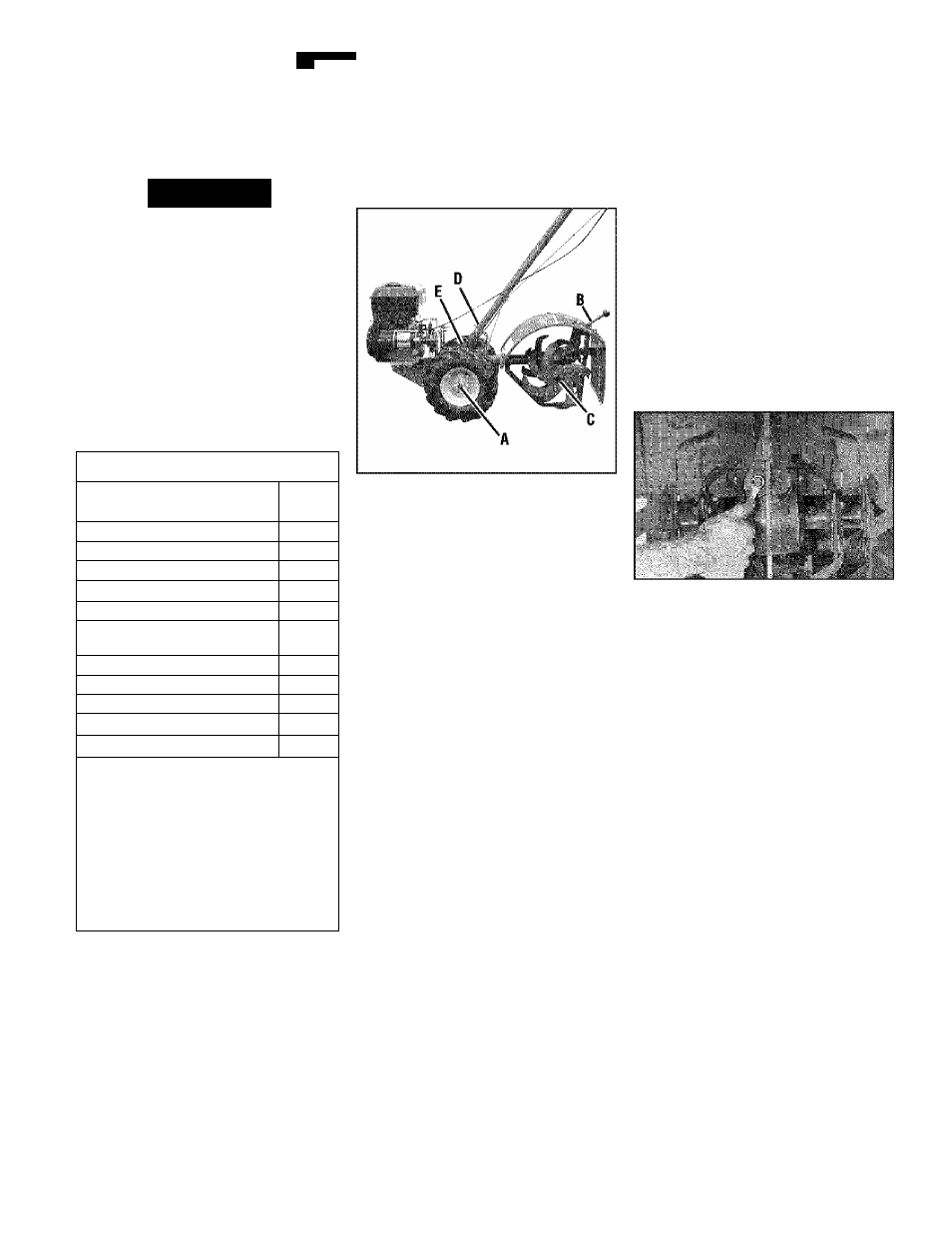
Figure 5-1: Lubrication points.
Proper lubrication of the tiller is an essen
tia! part of your maintenance program.
After every 10 operating hours, oil or
grease the lubrication points shown in
Figure 5-1 as described below.
Use a good quality lubricating oil (#30
weight engine ol! is suitable) and a good
quality general purpose grease (grease
that has a metal lubricant is preferred, If
available).
• Remove wheels, clean wheel shaft (A,
Figure 5-1) and appiy thin coating of
grease to shaft.
• Grease back, front and sides of depth
regulator lever (B, Figure 5-1).
• Remove tines, clean tine shafts (C,
Figure 5-1) and inspect for rust, rough
spots or burrs (especially around
holes). File or sand smooth and coat
ends of shaft with grease.
• Oil the threads on the handlebar height
adjustment screw (D, Figure 5-1).
• Oil the threads on the handlebar attach
ing screws (E, Figure 5-1).
CHECK HARDWARE
At least every 10 operating hours, check
the unit for loose or missing hardware
(screws, bolts, nuts, hairpin cotters, etc.).
Loose or missing hardware can lead to
equipment failure, poor performance or
oil leaks.
Be sure to check the three end cap
mounting screws located at the rear of the
transmission (Figure 5-2). Lift the tine
flap to service those screws.
Figure 5-2
CHECK TIRE PRESSURE
Check the air pressure in both tires.
Deflate or inflate both tires evenly to 15-
to-20 PSI (pounds per square Inch). Be
sure that both tires have the same air
pressure or the unit will tend to pull to
one side.