Video equipm ent connections – Onkyo TX-SV535 User Manual
Page 9
Attention! The text in this document has been recognized automatically. To view the original document, you can use the "Original mode".
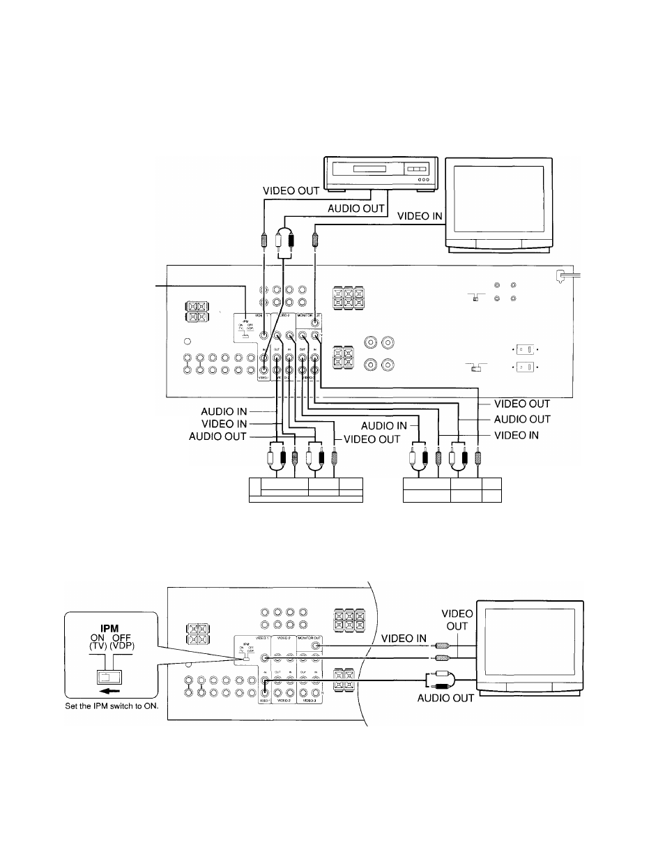
Video equipm ent connections
On each pair of input jacks, the lower jack (marked R: Red) corresponds to the
right channel, and the upper jack (marked L: White) to the left channel.
Please refer to the instruction manual of each component when making any connec
tions.
Video disc player
Monitor TV
The IPM switch is
normaiiy set to OFF.
Interference may be caused
between the TV and this unit,
if this interference occurs,
piace this unit and the TV as
far apart as possible. We do
not recommend the use of a
common TV/FM antenna (see
antenna section).
□
□
o
1 [
□! 1
„
Video cassette recorder
[J [
□1 1
Video cassette recorder
IPM system; The receiver’s power is automatically turned on when the TV is turned on. To use this function, connect the units as shown in the
diagram.
NOTES;
•
This unit will automatically switch on approximately three to five seconds after the TV comes on.
•
The 1PM function is not operating if the TV screen remains blank, even if the TV is swiched on.
•
In order to use the 1PM function, the TX-SV535 should be connected to the video input terminal on the TV.