Connection for multiple-room remote control – Onkyo TX-SV535 User Manual
Page 14
Attention! The text in this document has been recognized automatically. To view the original document, you can use the "Original mode".
Connection for Multiple-Room Remote Control
U.S.A. and Canadian models (Xantech Multiple-Room systems)
Do not plug in the power cord until all connections have been made.
When making connections 1, through 5 , be sure to connect the units as shown in the connection diagram beiows Do not make a mistake when
connecting the units.
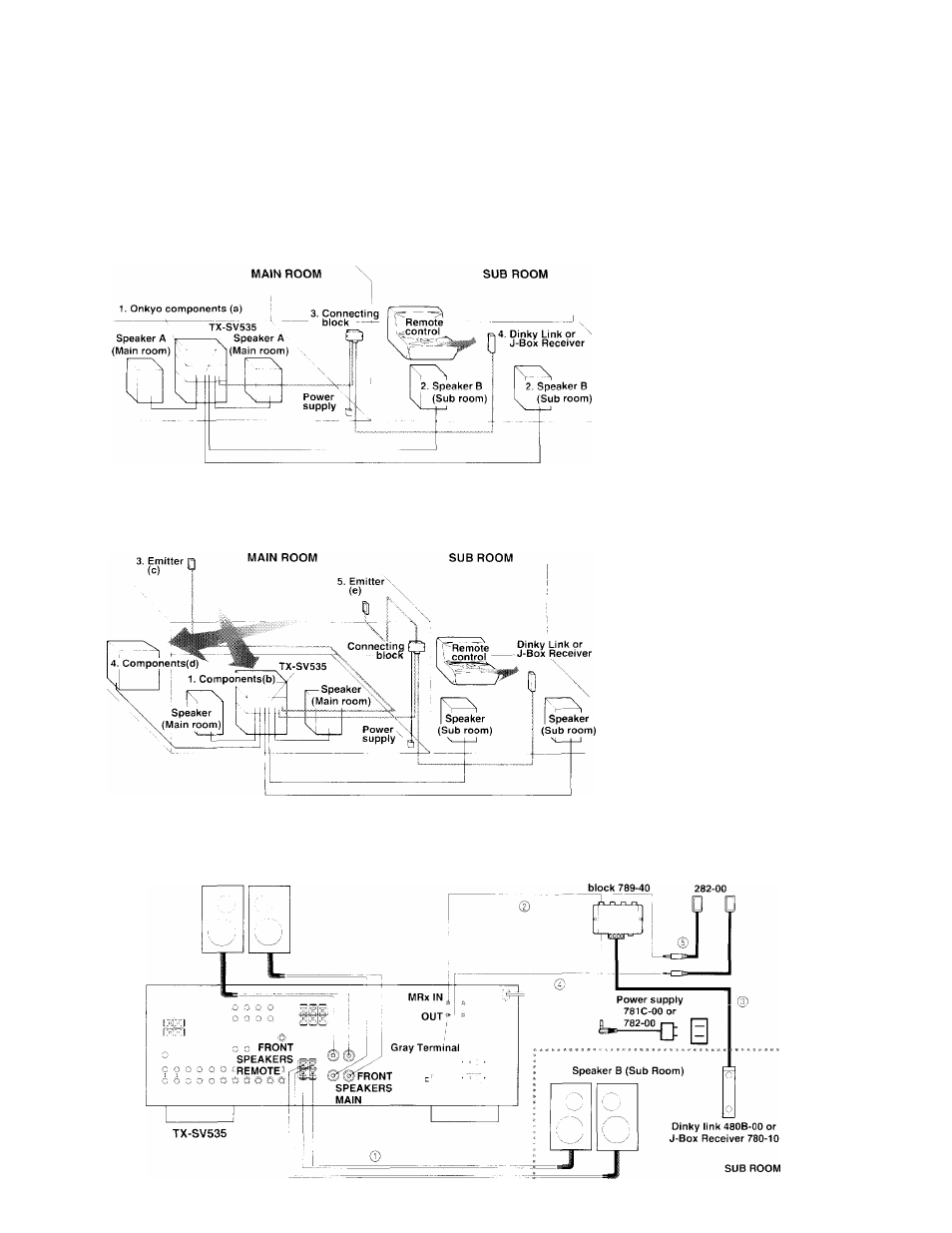
A. Operating components displaying Onkyo’s Ri mark from the sub-room
Components mounted in a rack should be connected as shown below to enable remote control operation.
1. Set up the components (a) displaying
Onkyo’s RI mark.
2.
Connect the speaker B cables to the
speaker terminal on the TX-SV535.
I
1
I
3. Install Connecting Block 789-40 in the
main room, then connect it to the TX-
SV535.
(:.2
.)
(Connect Power Supply 781C-00 or
782-00 to the Connecting Block.)
4.
Install Xantech’s ,1-Box Receiver 780-
10 or Dinky Link 480B-00 in the sub
room. then connect it to the Connect
ing Block in the main room. ( 3 )
B. Using a remote control to operate components not displaying Onkyo's RI mark from the sub-room
1.
Connect the components (b) to the
TX-SV535.
2.
Make the connections described above
in steps 2 through 4 of section A.
3.
Install Emitter 282-00 (c) so that its
sensor is directed toward these com
ponents. then connect it to the FX-
SV535. ( 4 )
■
Operating
components
which
are positioned out of the range of
the emitter installed as described
above
4.
Connect the components (d) to the
TX-SV535.
5.
Install another Emitter 282-00 (e) so
that its sensor is directed toward these
components, then connect it to the
Connecting Block 789-40. ( 5 )
Connection diagram
Speaker A (Main Room)
14
Connecting
Emitter