Installation, Location and clearances – Sears 9MPD User Manual
Page 5
Attention! The text in this document has been recognized automatically. To view the original document, you can use the "Original mode".
If your furnace remains off for an extended time, the pipes in your
home could freeze and burst, resulting in serious water damage.
Water may create a condition in which mold can grow in your
home. Certain types of mold have been reported to cause respi
ratory problems or other serious health risks. Remedial actions,
including immediately drying all wet items, should be taken quick
ly to help prevent the development of mold in your home.
If the structure will be unattended during cold weather you should
take these precautions.
1. Turn off the water supply to the structure and drain the wa
ter lines if possible and add an antifreeze for potable water
to drain traps and toilet tanks. Open faucets in appropriate
areas.
Have someone check the structure frequently during cold
weather to make sure it is warm enough to prevent pipes
from freezing. Instruct them on a service agency to call to
provide service, if required.
-or-
3.
Install a reliable remote sensing device that will notify
somebody of freezing conditions within the home.
Winter Shutdown
If you go away during the winter months and do not leave the heat
on in your home, the plastic transition box and the condensate
trap on the furnace must be protected from freeze damage.
(See
Figure 8
trough
Figure 17)
1.
Disconnect the OD rubber hose from the vent drain fit
ting that is located downstream of the combustion blower.
Insert a funnel into the hose and pour four{4) ounces of
sanitary type (RV) antifreeze into the condensate trap. Re
connect the %" OD rubber hose to the stub on the vent
drain fitting. Secure with the hose clamp.
2. Disconnect the ^/
4
" OD rubber hose from the condensate
trap. Insert a funnel into the hose and and pour four(4)
ounces of sanitary type (RV) antifreeze into the plastic
Transition box. Squeeze the hose together near the end
and quickly reconnect the ^/
4
" OD rubber hose to the stub
on the condensate trap. Secure with the hose clamp.
When you return home, your furnace will be ready to start, as it is
not necessary to drain the antifreeze from the furnace.
2. Installation
CARBON MONOXIDE POISONING HAZARD
Failure to properly vent this furnace or other appliances
can result in death, personal injury and/or property
damage.
This furnace can NOT be common vented or connected to
any type B, BW or L vent or vent connector, nor to any
portion of a factory-built or masonry chimney. If this
furnace
is
replacing
a
previously
common-vented
furnace, it may be necessary to resize the existing vent
and chimney to prevent oversizing problems for the other
remaining appliance(s). See Venting and Combustion Air
Check in Gas Vent Installation section. This furnace
MUST be vented to the outside.
Location and Clearances
4
.
Referto Figure lorFigure 2 for typical installation and ba
sic connecting parts required. Refer to Figure 4 for typical
horizontal direct vent installation and basic connecting
parts required. Supply and return air plenums and duct are
also required.
5. If furnace is a replacement, it is usually best to install the
furnace where the old one was. Choose the location or
evaluate the existing location based upon the minimum
clearance and furnace dimensions (Figure 3).
CAUTION
Special precautions MUST be made if installing furnace in an
area which may drop below freezing. This can cause
improper operation or damage to equipment. If furnace
environment has the potential of freezing, the drain trap and
drainline must be protected. The use of electric heat tape or
RV antifreeze is recommended for these installations. (See
"Condensate Trap Freeze Protection Section ")
Do
NOT
operate
furnace
in
a
corrosive
atmosphere
containing
chlorine,
fluorine
or
any
other
damaging
chemicals. Refer to Combustion & Ventilation Air section,
Contaminated Combustion Air.
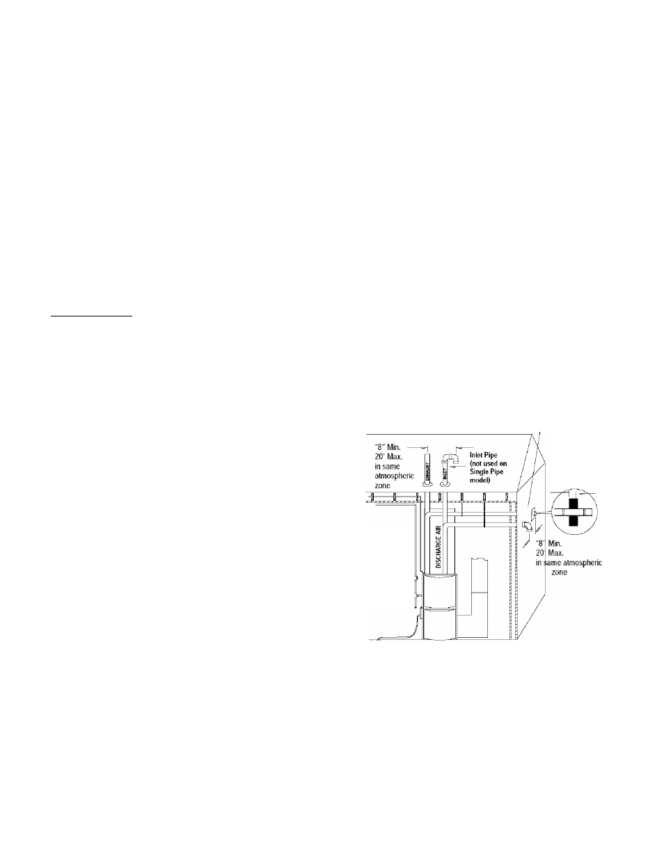
Figure 1
Typical Upflow Installation
Aluminum or non-rusting shield recommended. (See
Vent Termination Shielding for dimensions).
Coupling on ends of
exhaust pipe. Total
pipe & coupling out
side structure = 8"
Vent Pipes WIUST be
supported
Horizontally and
Vertically
* Increase minimum from 8" to 18” for cold climates (sustained temperatures
below 0°F).
25-23-
33
44001
1114
00
[U