Sears 9MPD User Manual
Page 14
Attention! The text in this document has been recognized automatically. To view the original document, you can use the "Original mode".
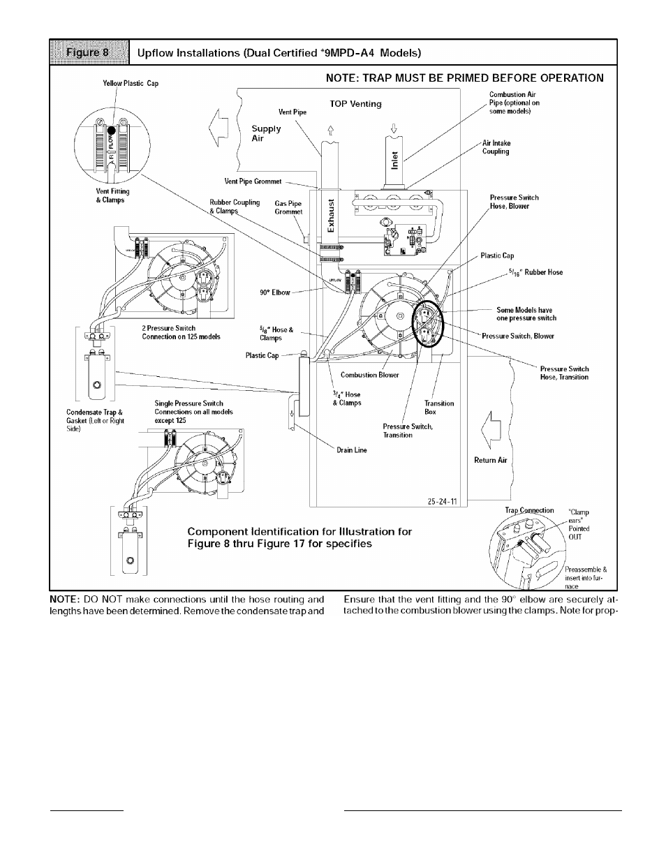
drain hoses from the furnace and secure the drain hoses to the
drain stubs on the trap with the hose clamps (position the clamps
as shown in
Figure 8).
Install the condensate trap/hose assem
bly to the furnace casing. Hook one side of the "clamp ears" on the
drain stub through the hole in the casing and push the condensate
trap into position. Secure with the two screws. Reconnect the
drain hoses to the stubs on the vent fitting and the plastic transi
tion and secure with the clamps.
Mount the condensate drain trap in a vertical position to either the
left or right side of the furnace using the two screws and gasket
that are provided. If needed, remove the hole plugs from the fur
nace side panel and relocate to the open set of holes in the oppo
site side panel.
NOTE: All gaskets and seals must be in place for sealed combus
tion applications._____________________________________
er alignment of the vent pipe through the furnace, the 90° elbow
must be installed with the "UPFLOW" lettering on the 90° elbow
facing out.
NOTE: The 90° elbow is approved for use inside the furnace
ONLY.
Plug the upper drain stub on the vent fitting with the yellow plastic
cap.
For left side venting, remove 90° elbow from the vent fitting by
loosening the clamp on the vent fitting. Securely attach vent fitting
to combustion blower.
NOTE: For left side venting, the vent fitting MUST be installed
with the airflow marking arrow pointed toward the vent pipe, with
the drain stub at a 5° to 10° downward slope.
Connect the PVC vent extension pipe to the vent fitting.
This pipe
has a built-in channel to assist vent condensate disposal.
Align the arrow on the PVC pipe with the airflow marking arrow on
the vent fitting. See label on the PVC pipe for proper installation.
44001
1114
00