Vertical & horizontal termination – Sears 9MPD User Manual
Page 45
Attention! The text in this document has been recognized automatically. To view the original document, you can use the "Original mode".
Vertical termination is preferred. Field supplied pipe and fittings
are required to complete the installation.
Figurn 44
Kit Components
Kit Contents;
3" Rain Cap or 2" Rain Cap
3" Diameter SDR-26 Pipe,
19
^/
2
“ Long or
4" Diameter SDR-26 Pipe,
37^Is"
Long,
2" Diameter SDR-26 Pipe, 31%" Long or
2
V
2
” Diameter SDR-26 Pipe, 24" Long,
3" Y Concentric Fitting or 2" Y Concentric Fitting
3" or 4” Dia.
/ SDR-26 Pipe
l3i,,
2" or 3" Dia.
Y Concentric Fitting
2 or 2^/2" Dia.
SDR-26 Pipe
2" or 3" Dia.
Rain Cap
25-22-03
Vertical & Horizontal Termination
1
.
Determine the pipe diameters required for the installation
from Table 10 and Table 11 and Figure 46.
2.
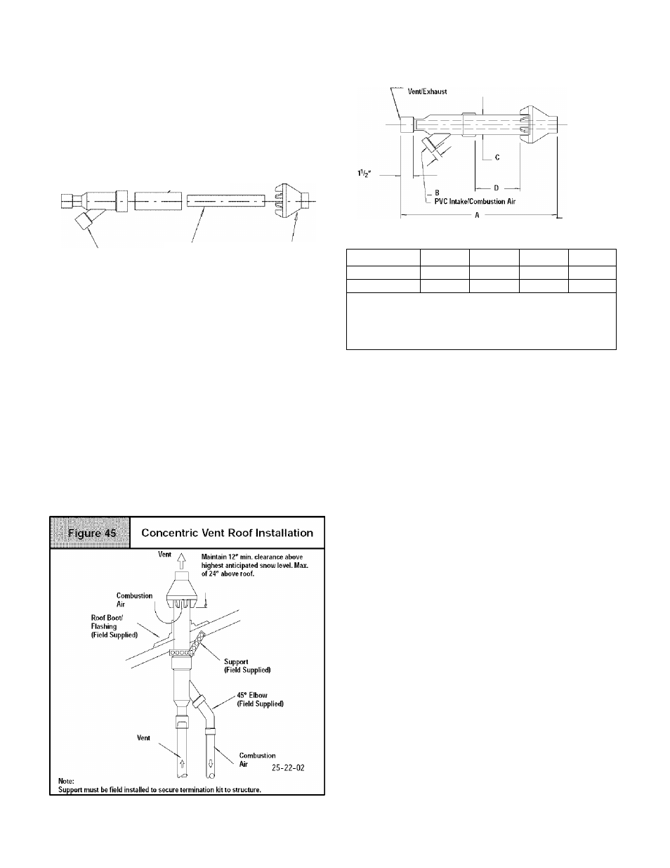
Determine the best location for the termination kit. See
Figure 45 for vertical termination or Figure 45 and
Figure 49 for horizontal termination. Roof termination is
preferred since it is less susceptible to damage, has re
duced intake contaminants and less visible vent vapor. For
side wall termination, consideration should be given to: 1)
possible damage from the vapors to plants/shrubs, other
equipment and building materials, 2) possible damage to
the terminal from foreign objects, 3) wind effects that may
cause recirculation of flue products, debris or light snow
and 4) visible vent vapor.
3.
Cut one 5 ' diameter hole through the structure for the
NAHA001CV Kit or one 4" diameter hole for the
NAHA002CV Kit .
4. Dimension D may be lengthened to 60" max. or shortened
by cutting the pipes to 12" min. Dimension A will change ac
cording to D dimension. (See Figure 46)
Figuro 46
Concentric
Vent
Dimensional
Drawing
EPVC
25-22-03
Model
A*
B
c
D”
NAHA001CV
WTe
3
4
T
2
21 Ve
NAHA002CV
33-^/g
2
3'/2
16'/e
* =
Dimension will change accordingly as dimension D is
lengthened or shortened.
*•
= Dimension D may be lengthened to 60” may also be
shortened by cutting the pipes provided in the kit to 12"
minimum
Table 10
Concentric Termination Kit
NAHA001CV & NAHA002CV Venting
Table for *9MPD Models
50,000, 75,000 & 80,000 Btuh Furnaces
NAHA002CV - 35' & (4) 90° elbows with 2" PVC pipe or
NAHA001CV - 65' & (4) 90° elbows with 3” PVC pipe
100,000 Btuh Furnace
NAHA001CV - 35' & (4) 90° elbows with 3" PVC pipe or
NAHA001CV - 65' & (4) 90° elbows with 3” PVC pipe &
Long Vent Kit (See Tech. Manual)
125,000 Btuh Furnace
NAHA001CV - 35' & (4) 90° elbows with 3" PVC pipe
1. Do not include the field supplied 45° elbow in the total elbow
count.
2. If more than four elbows are required, reduce the length of
both the inlet and the exhaust pipes five feet for each
additional elbow used.
3. Elbows are DWV long radius type for
2"
and 3" vents.
NOTE: Feet of pipe is whichever pipe run is the longest, either
inlet or outlet side.
44001 1114 00
[
45
)